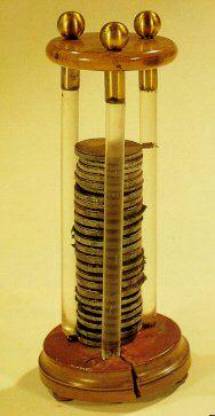
The connection between chemistry and electricity is a very old one, going back to Alessandro Volta's
discovery, in 1793, that electricity could be produced by placing two
dissimilar metals on opposite sides of a moistened paper.
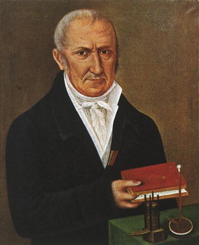 |
“I have the
pleasure of communicating to you, Sir, and through you to the Royal
Society, some striking results at which I have arrived in pursuing my
experiments on the electricity excited by the simple mutual contact of
metals of different sorts...”
|
 |
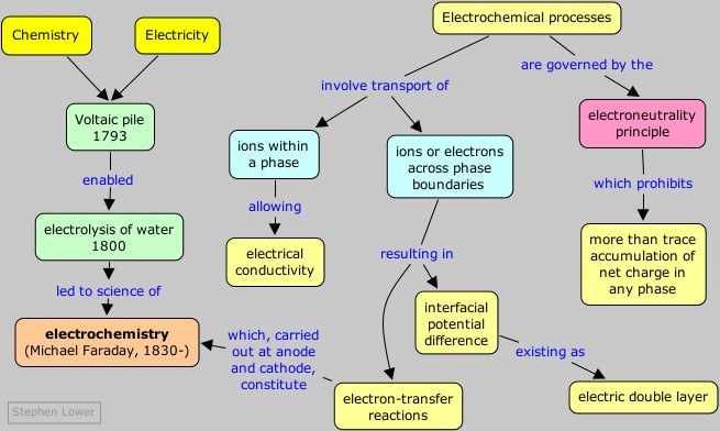
This was the first proof that water is composed of hydrogen and oxygen.This was surely one of the most significant experiments in the history of chemistry, for it implied that the atoms of hydrogen and oxygen were associated with positive and negative electric charges, which must be the source of the bonding forces between them. By 1812, the Swedish chemist Berzelius could propose that all atoms are electrified, hydrogen and the metals being positive, the nonmetals negative. In electrolysis, the applied voltage was thought to overpower the attraction between these opposite charges, pulling the electrified atoms apart in the form of ions (named by Berzelius from the Greek for "travelers"). It would be almost exactly a hundred years later before the shared electron pair theory of G.N. Lewis could offer a significant improvement over this view of chemical bonding.
Meanwhile the use of electricity as a means of bringing about chemical change continued to play a central role in the development of chemistry. Humphrey Davey prepared the first elemental sodium by electrolysis of a sodium hydroxide melt.
It was left to Davey's former assistant, Michael Faraday, to show that there is a direct relation between the amount of electric charge passed through the solution and the quantity of electrolysis products. James Clerk Maxwell immediately saw this as evidence for the "molecule of electricity", but the world would not be receptive to the concept of the electron until the end of the century.
Electroneutrality
Nature seems to strongly discourage any process that would
lead to an excess of positive or negative charge in matter. Suppose, for
example, that we immerse a piece of zinc metal in pure water. A small
number of zinc atoms go into solution as Zn ions, leaving their
electrons behind in the metal:
Zn(s) → Zn2+ + 2e–
As this process goes on, the electrons which remain in the
zinc cause a negative charge to build up within the metal which makes it
increasingly difficult for additional positive ions to leave the
metallic phase. A similar buildup of positive charge in the liquid phase
adds to this inhibition. Very soon, therefore, the process comes to a
halt, resulting in a solution in which the concentration of Zn2+ is still too low (around 10–10 M) to be detected by ordinary chemical means. |
| Transport of zinc ions from the metal to water; the build-up of negative charge in the metal (and positive charge in the solution) soon brings the process to a halt. |
There would be no build-up of this opposing charge in the two phases if the excess electrons could be removed from the metal or the positive ions consumed as the electrode reaction proceedes. For example, we could drain off the electrons left behind in the zinc through an external circuit that forms part of a complete electrochemical cell; this we will describe later. Another way to remove these same electrons is to bring a good electron acceptor (that is, an oxidizing agent) into contact with the electrode. A suitable acceptor would be hydrogen ions; this is why acids attack many metals. For the very active metals such as sodium, water itself is a sufficiently good electron acceptor.The degree of charge unbalance that is allowed produces differences in electric potential of no more than a few volts, and corresponds to unbalances in the concentrations of oppositely charged particles that are not chemically significant. There is nothing mysterious about this prohibition, known as the electroneutrality principle; it is a simple consequence of the thermodynamic work required to separate opposite charges, or to bring like charges into closer contact. The additional work raises the free energy change of the process, making it less spontaneous.
The only way we can get the oxidation of the metal to continue is to couple it with some other process that restores electroneutrality to the two phases. A simple way to accomplish this would be to immerse the zinc in a solution of copper sulfate instead of pure water. As you will recall if you have seen this commonly-performed experiment carried out, the zinc metal quickly becomes covered with a black coating of finely-divided metallic copper. The reaction is a simple oxidation-reduction process, a transfer of two electrons from the zinc to the copper:
Zn(s) → Zn2+ + 2e– Cu2+ + 2e– → Cu(s)
The dissolution of the zinc is no longer inhibited by a
buildup of negative charge in the metal, because the excess electrons
are removed from the zinc by copper ions that come into contact with it.
At the same time, the solution remains electrically neutral, since for
each Zn ion introduced to the solution, one Cu ion is removed. The net
reaction
Zn(s) + Cu2+ → Zn2+ + Cu(s)
quickly goes to completion.
Potential differences at interfaces
The transition region between two phases consists of a region of charge unbalance known as the electric double layer.
As its name implies, this consists of an inner monomolecular layer of
adsorbed water molecules and ions, and an outer diffuse region that
compensates for any local charge unbalance that gradually merges into
the completely random arrangement of the bulk solution. In the case of a
metal immersed in pure water, the electron fluid within the metal
causes the polar water molecules to adsorb to the surface and orient
themselves so as to create two thin planes of positive and negative
charge. If the water contains dissolved ions, some of the larger (and
more polarizable) anions will loosely bond (chemisorb) to the metal, creating a negative inner layer which is compensated by an excess of cations in the outer layer.Electrochemistry is the study of reactions in which charged particles (ions or electrons) cross the interface between two phases of matter, typically a metallic phase (the electrode) and a conductive solution, or electrolyte. A process of this kind can always be represented as a chemical reaction and is known generally as an electrode process. Electrode processes (also called electrode reactions) take place within the double layer and produce a slight unbalance in the electric charges of the electrode and the solution. Much of the importance of electrochemistry lies in the ways that these potential differences can be related to the thermodynamics and kinetics of electrode reactions. In particular, manipulation of the interfacial potential difference affords an important way of exerting external control on an electrode reaction.
The interfacial potential differences which develop in electrode-solution systems are limited to only a few volts at most. This may not seem like very much until you consider that this potential difference spans a very small distance. In the case of an electrode immersed in a solution, this distance corresponds to the thin layer of water molecules and ions that attach themselves to the electrode surface, normally only a few atomic diameters. Thus a very small voltage can produce a very large potential gradient. For example, a potential difference of one volt across a typical 10–8 cm interfacial boundary amounts to a potential gradient of 100 million volts per centimeter— a very significant value indeed!
Interfacial potentials are not confined to
metallic electrodes immersed in solutions; they can in fact exist
between any two phases in contact, even in the absence of chemical
reactions. In many forms of matter, they are the result of adsorption or
ordered alignment of molecules caused by non-uniform forces in the
interfacial region. Thus colloidal particles in aqueous suspensions
selectively adsorb a given kind of ion, positive for some colloids, and
negative for others. The resulting net electric charge prevents the
particles from coming together and coalescing, which they would
otherwise tend to do under the influence of ordinary van der Waals
attractions.
Interfacial potential differences are not directly observable.The
usual way of measuring a potential difference between two points is to
bring the two leads of a voltmeter into contact with them. It's simple
enough to touch one lead of the meter to a metallic electrode, but there
is no way you can connect the other lead to the solution side of the
interfacial region without introducing a second electrode with its own
interfacial potential, so you would be measuring the sum of two
potential differences. Thus single electrode potentials, as they are commonly known, are not directly observable.What we can observe, and make much use of, are potential differences between pairs of electrodes in electrochemical cells. This is the topic of the next page in this series.
Summary
Make sure you thoroughly understand the following essential ideas
which have been presented above. It is especially imortant that you
know the precise meanings of all the highlighted terms in the context of
this topic.- Electroneutrality principle - Bulk matter cannot have a chemically-significant unbalance of positive and negative ions.
- Dissolution of a metal in water can proceed to a measurable extent only if some means is provided for removing the excess negative charge that remains. This can be by electron-acceptor ions in solution, or by drawing electrons out of the metal through an external circuit.
- Interfacial potentials - these exist at all phase boundaries. In the case of a metal in contact with an electrolyte solution, the interfacial region consists of an electric double layer.
- The potential difference between a metal and the solution is almost entirely located across the very thin double layer, leading to extremely large potential gradients in this region.
References
More on the electric double layer (Cambridge University)
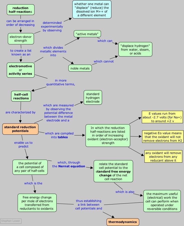
Concept Map
 This arrangement is called a galvanic cell.
A typical cell might consist of two pieces of metal, one zinc and the
other copper, each immersed each in a solution containing a dissolved
salt of the corresponding metal. The two solutions are separated by a
porous barrier that prevents them from rapidly mixing but allows ions to
diffuse through.
This arrangement is called a galvanic cell.
A typical cell might consist of two pieces of metal, one zinc and the
other copper, each immersed each in a solution containing a dissolved
salt of the corresponding metal. The two solutions are separated by a
porous barrier that prevents them from rapidly mixing but allows ions to
diffuse through.If we connect the zinc and copper by means of a metallic conductor, the excess electrons that remain when Zn2+ ions emerge from the zinc in the left cell would be able to flow through the external circuit and into the right electrode, where they could be delivered to the Cu2+ ions which become "discharged", that is, converted into Cu atoms at the surface of the copper electrode. The net reaction is the oxidation of zinc by copper(II) ions:
Zn(s) + Cu2+ → Zn2+ + Cu(s)
but this time, the oxidation and reduction steps (half reactions) take place in separate locations:
left electrode:
|
Zn(s) → Zn2+ + 2e– | oxidation |
right electrode:
|
Cu2+ + 2e–→ Cu(s) | reduction |
Electrochemical cells allow measurement and control of a redox reaction.
The reaction can be started and stopped by connecting or disconnecting the two electrodes. If we place a variable resistance in the circuit, we can even control the rate of the net cell reaction by simply turning a knob. By connecting a battery or other source of current to the two electrodes, we can force the reaction to proceed in its non-spontaneous, or reverse direction.By placing an ammeter in the external circuit, we can measure the amount of electric charge that passes through the electrodes, and thus the number of moles of reactants that get transformed into products in the cell reaction.
Electric charge q is measured in coulombs. The amount of charge carried by one mole of electrons is known as the faraday, which we denote by F. Careful experiments have determined that 1 F = 96467 c. For most purposes, you can simply use 96,500 coulombs as the value of the faraday.
When we measure electric current, we are measuring the rate at which electric charge is transported through the circuit. A current of one ampere corresponds to the flow of one coulomb per second.
Transport of charge within the cell
 For
the cell to operate, not only must there be an external electrical
circuit between the two electrodes, but the two electrolytes (the
solutions) must be in contact. The need for this can be understood by
considering what would happen if the two solutions were physically
separated. Positive charge (in the form of Zn2+) is added to the electrolyte in the left compartment, and removed (as Cu2+)
from the right side, causing the solution in contact with the zinc to
acquire a net positive charge, while a net negative charge would build
up in the solution on the copper side of the cell. These violations of electroneutrality would make it more difficult (require more work) to introduce additional Zn2+
ions into the positively-charged electrolyte or for electrons to flow
into the right compartment where they are needed to reduce the Cu2+ ions, thus effectively stopping the reaction after only a chemically insignificant amount has taken place.
For
the cell to operate, not only must there be an external electrical
circuit between the two electrodes, but the two electrolytes (the
solutions) must be in contact. The need for this can be understood by
considering what would happen if the two solutions were physically
separated. Positive charge (in the form of Zn2+) is added to the electrolyte in the left compartment, and removed (as Cu2+)
from the right side, causing the solution in contact with the zinc to
acquire a net positive charge, while a net negative charge would build
up in the solution on the copper side of the cell. These violations of electroneutrality would make it more difficult (require more work) to introduce additional Zn2+
ions into the positively-charged electrolyte or for electrons to flow
into the right compartment where they are needed to reduce the Cu2+ ions, thus effectively stopping the reaction after only a chemically insignificant amount has taken place.In order to sustain the cell reaction, the charge carried by the electrons through the external circuit must be accompanied by a compensating transport of ions between the two cells. This means that we must provide a path for ions to move directly from one cell to the other. This ionic transport involves not only the electroactive species Cu2+ and Zn2+, but also the counterions, which in above example are nitrate, NO3–.
Thus the positive charge resulting from the release of Zn2+ in the left compartment could be compensated by the drift of these ions into the right side, or equally well by diffusion of nitrate ions from the righ-hand cell to the left.
More detailed studies reveal that both processes occur, and that the relative amounts of charge carried through the solution by positive and negative ions depends on their relative mobilities, which express the velocity with which the ions are able to make their way through the solution. Since negative ions tend to be larger than positive ions, the latter tend to have higher mobilities and carry the larger fraction of charge. In the diagram below, sodium and sulfate ions serve the same function. (Neither of these ions is able to undergo oxidation or reduction in the presence of water.)
In the simplest cells, the barrier between the two solutions can be a porous membrane, but for precise measurements, a more complicated arrangement, known as a salt bridge, is used. The salt bridge consists of an intermediate compartment filled with a concentrated solution of KCl and fitted with porous barriers at each end. The purpose of the salt bridge is to minimize the natural potential difference, known as the junction potential, that develops (as mentioned in the previous section) when any two phases (such as the two solutions) are in contact. This potential difference would combine with the two half-cell potentials so as introduce a degree of uncertainty into any measurement of the cell potential. With the salt bridge, we have two liquid junction potentials instead of one, but they tend to cancel each other out.
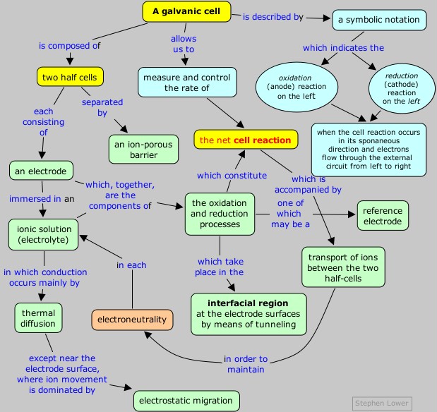
Cell description conventions
In order to make it easier to describe a given electrochemical
cell, a special symbolic notation has been adopted. In this notation
the cell we described above would be
Zn(s) | Zn2+(aq) || Cu2+(aq) | Cu(s)
There are several other conventions relating to cell notation and nomenclature that you are expected to know:- The anode is where oxidation occurs, and the cathode is the site of reduction. In an actual cell, the identity of the electrodes depends on the direction in which the net cell reaction is occurring.
- If electrons flow from the left electrode to the right electrode (as depicted in the above cell notation) when the cell operates in its spontaneous direction, the potential of the right electrode will be higher than that of the left, and the cell potential will be positive.
- "Conventional current flow" is from positive to negative, which is opposite to the direction of the electron flow. This means that if the electrons are flowing from the left electrode to the right, a galvanometer placed in the external circuit would indicate a current flow from right to left.
Electrodes and electrode reactions
An electrode reaction refers to the net oxidation or
reduction process that takes place at an electrode. This reaction may
take place in a single electron-transfer step, or as a succession of two
or more steps. The substances that receive and lose electrons are
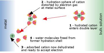
called the electroactive species. Fig. 4: Electron transfer at an anode
 This
process takes place within the very thin interfacial region at the
electrode surface, and involves quantum-mechanical tunneling of
electrons between the electrode and the electroactive species. The work
required to displace the H2O molecules in the hydration spheres of the ions constitutes part of the activation energy of the process.
This
process takes place within the very thin interfacial region at the
electrode surface, and involves quantum-mechanical tunneling of
electrons between the electrode and the electroactive species. The work
required to displace the H2O molecules in the hydration spheres of the ions constitutes part of the activation energy of the process. Ion-ion electrodes
Many electrode reactions involve only ionic species, such as Fe2+ and Fe3+. If neither of the electroactive species is a metal, some other metal must serve as a conduit for the supply or removal of electrons from the system. In order to avoid complications that would arise from electrode reactions involving this metal, a relatively inert substance such as platinum is commonly used. Such a half cell would be represented as
Pt(s) | Fe3+(aq), Fe2+(aq) || ...
and the half-cell reaction would be
Fe2+(aq) → Fe3+ (aq) + e–
The reaction occurs at the surface of the electrode (Fig 4
above). The electroactive ion diffuses to the electrode surface and
adsorbs (attaches) to it by van der Waals and coulombic forces. In doing
so, the waters of hydration that are normally attached to any ionic
species must be displaced. This process is always endothermic, sometimes
to such an extent that only a small fraction of the ions be able to
contact the surface closely enough to undergo electron transfer, and the
reaction will be slow. The actual electron-transfer occurs by
quantum-mechanical tunnelling.Gas electrodes
Some electrode reactions involve a gaseous species such as H2, O2, or Cl2. Such reactions must also be carried out on the surface of an electrochemically inert conductor such as platinum. A typical reaction of considerable commercial importance is
Cl–(aq) → ½ Cl2(g) + e–
Similar reactions involving the oxidation of Br2 or I2 also take place at platinum surfaces.Insoluble–salt electrodes
A typical electrode of this kind consists of a silver wire covered with a thin coating of silver chloride, which is insoluble in water. The electrode reaction consists in the oxidation and reduction of the silver:
AgCl(s) + e– → Ag(s) + Cl–(aq)
The half cell would be represented as
... || Cl– (aq) | AgCl (s) | Ag (s)
Although the usefulness of such an electrode may not be
immediately apparent, this kind of electrode finds very wide application
in electrochemical measurements, as we shall see later.
Reference Electrodes
In most electrochemical experiments our interest is concentrated on
only one of the electrode reactions. Since all measurements must be on a
complete cell involving two electrode systems, it is common practice to
employ a reference electrode as the other half of the cell.
The major requirements of a reference electrode are that it be easy to
prepare and maintain, and that its potential be stable. The last
requirement essentially means that the concentration of any ionic
species involved in the electrode reaction must be held at a fixed
value. The most common way of accomplishing this is to use an electrode
reaction involving a saturated solution of an insoluble salt of the ion.
One such system, the silver-silver chloride electrode has already been
mentioned:
Ag | AgCl(s) | Cl–(aq) || ...
Ag(s) + Cl–(aq) →AgCl(s) + e–
This electrode usually takes the form of a piece of silver wire
coated with AgCl. The coating is done by making the silver the anode in
an electrolytic cell containing HCl; the Ag+ ions combine with Cl– ions as fast as they are formed at the silver surface.
The other common reference electrode is the calomel electrode; calomel is the common name for mercury(I) chloride.
Hg | Hg2+(aq) | KCl || ... Hg(l) + Cl– → ½ HgCl2(s) + e–
The potentials of both of these electrodes have been very accurately
determined against the hydrogen electrode. The latter is seldom used in
routine electrochemical measurements because it is more difficult to
prepare; the platinum surface has to be specially treated by preliminary
electrolysis. Also, there is need for a supply of hydrogen gas which
makes it somewhat cumbersome and hazardous.
Summary and additional notes
Make sure you thoroughly understand the following essential ideas
which have been presented above. It is especially imortant that you
know the precise meanings of all the highlighted terms in the context of
this topic.- A galvanic cell (sometimes more appropriately called a voltaic cell) consists of two half-cells joined by a salt bridge or some other path that allows ions to pass between the two sides in order to maintain electroneutrality.
- The conventional way of representing an electrochemical cell of any kind is to write the oxidation half reaction on the left and the reduction on the right. Thus for the reaction
Zn(s) + Cu2+ → Zn2+ + Cu(s)we writeZn(s) | Zn2+(aq) || Cu2+(aq) | Cu(s)in which the single vertical bars represent phase boundaries. The double bar denotes a liquid-liquid boundary which in laboratory cells consists of a salt bridge or in ion-permeable barrier. If the net cell reaction were written in reverse, the cell notation would become
Cu(s) | Cu2+(aq) || Zn 2+(aq) | Zn (s)Remember: the Reduction process is always shown on the Right.
- The transfer of electrons between an electrode and the solution takes place by quantum-mechanical tunneling at the electrode surface. The energy required to displace water molecules from the hydration shell of an ion as it approaches the electrode surface constitutes an activation energy which can slow down the process.
Concept Map
It has long been known that some
metals are more "active" than others in the sense that a more active
metal can "displace" a less active one from a solution of its salt. The
classic example is the one we have already mentioned on the preceding
page:
Zn(s) + Cu2+ → Zn2+ + Cu(s)
Here zinc is more active because it can displace
(precipitate) copper from solution. If you immerse a piece of metallic
zinc in a solution of copper sulfate, the surface of the zinc quickly
becomes covered with a black coating of finely-divided copper, and the
blue color of the hydrated copper(II) ion diminishes.
Similar comparisons of other metals made it possible to arrange
them in the order of their increasing electron-donating (reducing)
power. This sequence became known as the electromotive or activity series of the metals.
|
The most active (most strongly
reducing) metals appear on top, and least active metals appear on the
bottom. A more active metal (such as Zn) will donate electrons to the
cation of a less active metal (Cu2+, for example.) Notice the special role of hydrogen here; although H2 does not have the physical properties of a metal, it is capable of being "displaced" (a rather archaic term seldom used in modern chemistry) from H2O or H+-containing (acidic) solutions. Note that the "active" metals are all "attacked by acids"; what this really means is that they are capable of donating electrons to H+.
(This table was adapted from a now-disappeared one at General Chemistry Online .)
|
 ) → 2 LiOH(aq) + H2(g)
The activity series has long been used to predict the direction of oxidation-reduction reactions; see here
for a nicely-done table with explanatory material. Consider, for
example, the oxidation of Cu by metallic zinc that we have mentioned
previously. The fact that zinc is near the top of the activity series
means that this metal has a strong tendency to lose electrons. By the
same token, the tendency of Zn to accept electrons is relatively small.
Copper, on the other hand, is a poorer electron donor, and thus its
oxidized form, Cu, is a fairly good electron acceptor. We would
therefore expect the reaction
The above table is of limited practical use because it does not take into account the concentrations of the dissolved species. In order to treat these reactions quantitatively, it is convenient to consider the oxidation and reduction steps separately.
in which "right" and "left" refer to the cell notation convention ("reduction on the right")
and not, of course, to the physical orientation of a real cell in the
laboratory. If we expand the above expression we see that the cell
potential
The reference cell that has universally been adopted for this purpose is the hydrogen half-cell
In order to measure the relative potential of some other electrode couple M2+/M, we can set up a cell
Standard [reduction] potentials are commonly denoted by the symbol E°. E°
values for hundreds of electrodes have been determined (mostly in the
period 1925-45, during which time they were referred to as "oxidation
potentials") and are usually tabulated in order of increasing tendency
to accept electrons (increasing oxidizing power.)
Zn(s) + Cu2+ → Zn2+ + Cu(s)
to proceed in the direction indicated, rather than in the reverse
direction. An old-fashioned way of expressing this is to say that "zinc
will displace copper from solution".The above table is of limited practical use because it does not take into account the concentrations of the dissolved species. In order to treat these reactions quantitatively, it is convenient to consider the oxidation and reduction steps separately.
Standard half-cell potentials
When a net reaction proceeds in an electrochemical cell,
oxidation occurs at one electrode (the anode) and reduction takes place
at the other electrode (the cathode.) We can think of the cell as
consisting of two half-cells joined together by an external circuit
through which electrons flow and an internal pathway that allows ions to
migrate between them so as to preserve electroneutrality.Reduction potentials
Each half-cell has associated with it an electrode-solution potential difference whose magnitude depends on the nature of the particular electrode reaction and on the concentrations of the dissolved electroactive species. The sign of this potential difference depends on the direction (oxidation or reduction) in which the electrode reaction proceeds. In order express them in a uniform way, we adopt the convention that half-cell potentials are always defined for the reduction direction. Thus the half-cell potential for the Zn/Zn2+ electrode (or couple as it is sometimes called) always refers to the reduction reaction
Zn2+ + 2e– → Zn(s)
In the cell Zn(s) | Zn2+(aq) || Cu2+(aq) | Cu(s)
the zinc appears on the left side, indicating that it is being
oxidized, not reduced. For this reason, the potential difference
contributed by the left half-cell has the opposite sign to its
conventional half-cell potential. More generally, we can define the cell
potential or cell EMF as| Ecell = ΔV = Eright – Eleft |
(1)
|
Ecell = VCu – Vsolution + Vsolution – VZn
is just the difference between the two half-cell potentials Eright and Eleft.Reference half-cells
The fact that individual half-cell potentials are not directly measurable does not prevent us from defining and working with them. Although we cannot determine the absolute value of a half-cell potential, we can still measure its value in relation to the potentials of other half cells. In particular, if we adopt a reference half-cell whose potential is arbitrarily defined as zero, and measure the potentials of various other electrode systems against this reference cell, we are in effect measuring the half-cell potentials on a scale that is relative to the potential of the reference cell.The reference cell that has universally been adopted for this purpose is the hydrogen half-cell
Pt | ½ H2(g) | H+(aq) || ...
in which hydrogen gas is allowed to bubble over a platinum
electrode having a specially treated surface which catalyzes the
reaction
½ H2(g) → H+ + e–
When this electrode is operated under standard conditions of 1 atm H2 pressure, 25°C, and pH = 0, it becomes the standard hydrogen electrode, sometimes abbreviated SHE.In order to measure the relative potential of some other electrode couple M2+/M, we can set up a cell
Pt | H2(g) | H+ || M2+ (aq) | M(s)
whose net reaction is
H2(g) + M2+(aq) → 2H+ + M(s)
the potential difference between the platinum and M electrodes will be
Ecell = VM – Vsolution + Vsolution – V Pt
but since the difference Vsolution – V Pt is by definition zero for the hydrogen half-cell, the cell potential we measure corresponds to
Ecell = VM – Vsolution
which is just the potential (relative to that of the SHE) of the half-cell whose reaction is
M2+ + 2e– → M(s)
 |
Measurement of a standard reduction potential. The M2+/M half-cell is on the left, and the standard hydrogen cell is on the right. The two half-cells are joined through the salt bridge in the middle. The more "active" the metal M (the greater its tendency to donate electrons to H+), the more negative will be Ecell = ΔV = Eright – Eleft |
Table 2: some standard reduction potentials
A much more extensive table can be found here. Note particularly that
|
|
Given the E° values for two half reactions, you can easily predict the potential difference of the corresponding cell: simply add the reduction potential of the reduction half-cell to the negative of the reduction potential (that is, to the oxidation potential) of the oxidation reaction.
Problem Example 1
Find the standard potential of the cell
Solution: The net reaction corresponding to this cell will be
Cu(s) | Cu2+ || Cl– | AgCl(s) | Ag(s)
and predict the direction of electron flow when the two electrodes are connected.Solution: The net reaction corresponding to this cell will be
2 Ag(s) + 2 Cl–(aq) + Cu2+(aq) → AgCl(s) + Cu(s)
Since this involves the reverse of the AgCl reduction, we must reverse the corresponding half-cell potential:
Ecell = (.337 – .222) v = .115 v
Since this potential is positive, the reaction will proceed to
the right; electrons will be withdrawn from the copper electrode and
flow through the external circuit into the silver electrode. Note
carefully that in combining these half-cell potentials, we did not
multiply E° the for the Cu2+/Cu couple by two. The reason for this will be explained later.
Cell potentials and free energy
From the above, it should be apparent that the potential
difference between the electrodes of a cell is a measure of the tendency
for the cell reaction to take place: the more positive the cell
potential, the greater the tendency for the reaction to proceed to the
right. But we already know that the standard free energy change
expresses the tendency for any kind of process to occur under the
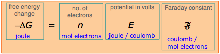
conditions of constant temperature and pressure. Thus ΔG° and E° measure the same thing, and are related in a simple way:
ΔG° = –nFE°
|
(2)
|
-
The negative sign on the right indicates that a positive cell potential (according to the sign convention discussed previously) implies a negative free energy change, and thus that the cell reaction will spontaneously proceed to the right.
-
Electrical work is done when an electric charge q moves through a potential difference ΔV. The right side of Eq. 2 refers to the movement of n moles of charge across the cell potential E°, and thus has the dimensions of work.
-
The value of ΔG° expresses the maximum useful work that a system can do on the surroundings.
"Useful" work is that which can be extracted from the cell by
electrical means to operate a lamp or some other external device. This
excludes any P-V work that is simply a consequence of volume
change (which could conceivably be put to some use!) and which would be
performed in any case, even if the reactants were combined directly.
This quantity of work –ΔG° can only be extracted from the system under
the limiting conditions of a thermodynamically reversible change, which for an electrochemical cell implies zero current. The more rapidly the cell operates, the less electrical work it can supply.
- If F is expressed in coulombs per mole of electrons, the electrical work is in joules per mole. To relate these units to electrical units, recall that the coulomb is one amp-sec, and that power, which is the rate at which work is done, is measured in watts, which is the product of amps and volts.
1 J = 1 watt-sec = 1 (amp-sec) × volts
Thus the volt has the
dimensions of joules/coulomb– the energy produced per quantity of charge
passing through the cell. Because voltage is the quotient of two
extensive quantities, it is itself intensive. When we multiply
the anodic and cathodic half-reactions by the stoichiometric factors
required to ensure that each involves the same quantity of charge, the
free energy change and the number of coulombs both increase by the same
factor, leaving the potential (voltage) unchanged. This explains why we
do not have to multiply the E°s of the anode and cathode reactions by stoichiometric factors when we are finding the potential of a complete cell.
If Eq. 2 is solved for E°, we have
(3)
|
To see this more clearly, consider the cell
Cu(s) | Cu2+ || Cl– | AgCl(s) | Ag(s)
for which we list the standard reduction potentials and ΔG°s of the half-reactions:
reaction
|
E°
|
-nFE°= ΔG°
|
| cathode: 2 × [AgCl(s) + e– → Ag(s) + Cl–] anode: Cu(s) → Cu2+ + 2 e– |
+.222 v –(+.337) v |
–42800 J +65000 J |
| net: 2 Ag(s) + 2 Cl–(aq) + Cu2+(aq) → AgCl(s) + Cu(s) cell: Cu(s) | Cu2+(aq) || AgCl(s) | Cl–(aq) | Ag(s) |
–.115 v | +22200 J |
When the electrons don't cancel out
Note, however, that if we are combining two half reactions to obtain a third half reaction, the E° values are not additive, since this third half-reaction is not accompanied by another half reaction that causes the charges to cancel. Free energies are always additive, so we combine them, and use ΔG° = –nFE° to find the cell potential.
Problem Example 2
Calculate E° for the electrode Fe3+/Fe(s) from the standard potential of the couples Fe3+/Fe2+ and Fe2+/Fe(s)
Solution: Tabulate the values and calculate the ΔG°s as follows:
The free energy for half-reaction (iii) is .109nF, so E°3 = –.109/3 = –.036 v
Solution: Tabulate the values and calculate the ΔG°s as follows:
| (i) Fe3+ + e– → Fe2+ | E°1 = .771 v , ΔG°1 = –.771 F |
| (ii) Fe2+ + 2 e– → Fe(s) | E°2= –.440 v , ΔG°2 = +.880 F |
| (iii) Fe3+ + 3 e– → Fe(s) | E°3 = ? , ΔG°3 = +.109 F |
The free energy for half-reaction (iii) is .109nF, so E°3 = –.109/3 = –.036 v
The fall of the electron
A table of standard half-cell potentials summarizes a large
amount of chemistry, for it expresses the relative powers of various
substances to donate and accept electrons by listing reduction
half-reactions in order of increasing E° values, and thus of increasing
spontaneity. The greater the value of E°, the greater the tendency of
the substance on the left to acquire electrons, and thus the stronger
this substance is as an oxidizing agent.If you have studied elementary chemical thermodynamics, you will have learned about the role that a quantity called the Gibbs free energy, usually referred to as simply the "free energy", plays in determining the direction of any chemical change. The rule is that all spontaneous change (that is, all reactions that proceed to the "right") is associated with a fall in the free energy, and the greater the degree of that fall (ΔG°), the greater will be the tendency for the reaction to take place.
Since oxidation-reduction processes involve the transfer of an electron from a donor to an acceptor, it makes sense to focus on the electron and to consider that it falls from a higher-free energy environment (the reductant, or "source") to a lower-free energy one (the oxidant, or "sink".)If you are not familiar with the concept of free energy, just think of it as something like potential energy, which similarly decreases when spontaneous mechanical events occur, such as the dropping of a weight.
As can be seen from the diagram below, this model makes it far easier to predict what will happen when two or more oxidants and reducants are combined; the electron "falls" as far as it can, filling up oxidizing agents (sinks) from the bottom up, very much in the same way as electrons fill atomic orbitals as we build up larger atoms.
 |
Electron-free energy diagram of redox couples
This chart is essentially an abbreviated form of a
table of standard potentials in which the various couples are displayed
on a vertical scale corresponding toE° = –ΔG°/nF. Any available sink on the right side will tend to drain electrons from a source above it. For example, immersion of metallic zinc in a solution of CuSO4 will result in the reduction of Cu2+ to metallic copper (red arrows.) Similarly, addition of chlorine to water will tend to oxidize the water, producing O2 and Cl– (blue arrows.) Note especially the positions of the H2/ H+ and H2O/O2,H+ couples on this chart, as they define the range of E°s for substances that will not decompose water (green region.) |
A more detailed table with a more complete explanation can be seen on the "Fall of the electron" tutorial page; it is strongly recommended that you take the time to acquire a thorough understanding of this concept.
At this point, it might be worth calling your attention to the
similar way of depicting acid-base reactions as representing the "fall
of the proton" as shown below and described much more thoroughly here.  |
Proton-free energy diagram of acid-base systems
Acids are proton sources (donors), bases are proton sinks.
Protons "fall" (in free energy) whenever a base is present that
presents proton-empty free energy levels. The red arrows show what
happens when acetic acid is titrated with a strong base; the results are
acetate ion and water. Note here again the crucial role of water, both
as a proton acceptor (forming hydronium ion) and as a proton donor
(forming hydroxide ion.) Note also that the pH of a solution is a direct
measure of the average free energy of protons in the solution (relative
to H3O+.) |
An important difference between proton transfer and electron transfer
reactions is that the latter can vary greatly in speed, from almost
instantaneous to so slow as to be unobservable. Acid-base reactions are
among the fastest known.
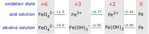 The formulas of the species that represent each oxidation state
of the element are written from left to right in order of decreasing
oxidation number, and the standard potential for the reduction of each
species to the next on the right is written in between the formulas.
Potentials for reactions involving hydrogen ions will be pH dependent,
so separate diagrams are usually provided for acidic and alkaline
solutions (effective hydrogen ion concentrations of 1M and 10–14 M, respectively).
The formulas of the species that represent each oxidation state
of the element are written from left to right in order of decreasing
oxidation number, and the standard potential for the reduction of each
species to the next on the right is written in between the formulas.
Potentials for reactions involving hydrogen ions will be pH dependent,
so separate diagrams are usually provided for acidic and alkaline
solutions (effective hydrogen ion concentrations of 1M and 10–14 M, respectively).
The more positive the reduction potential, the greater will be the tendency of the species on the left to be reduced to the one on the right. To see how Latimer diagrams are used, look first at the one for iron in acid solution. The line connecting Fe3+ and Fe2+ represents the reaction
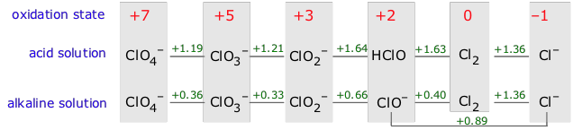 When the potential on the left of a species is less positive than
that on the right. This indicates that the species can oxidize and
reduce itself, a process known as disproportionation. As an example, consider Cl2 in alkaline solution. The potential for its reduction to Cl–
is sufficiently positive (+1.36 v) to supply the free energy necessary
for the oxidation of one atom of chlorine to hypochlorite. Thus
elemental chlorine is thermodynamically unstable with respect to
disproportionation in alkaline solution, and the same it true of the
oxidation product, ClO– (hypochlorite ion).
When the potential on the left of a species is less positive than
that on the right. This indicates that the species can oxidize and
reduce itself, a process known as disproportionation. As an example, consider Cl2 in alkaline solution. The potential for its reduction to Cl–
is sufficiently positive (+1.36 v) to supply the free energy necessary
for the oxidation of one atom of chlorine to hypochlorite. Thus
elemental chlorine is thermodynamically unstable with respect to
disproportionation in alkaline solution, and the same it true of the
oxidation product, ClO– (hypochlorite ion).
 Behavior of chlorine in water
Bear in mind that many oxidation-reduction reactions, unlike most
acid-base reactions, tend to be very slow, so the fact that a species is
thermodynamically unstable does not always mean that it will quickly
decompose. Thus the two reactions shown in the figure are normally very
slow.
Suppose, for example, that we reduce the concentration of Zn2+ in the Zn/Cu cell from its standard effective value of 1M to an to a much smaller value:
The relation between the actual cell potential E and the standard potential E° is developed in the following way. We begin with the equation derived previously which relates the standard free energy change (for the complete conversion of products into reactants) to the standard potential
This is the very important Nernst equation which relates
the cell potential to the standard potential and to the activities of
the electroactive species. Notice that the cell potential will be the
same as E° only if Q is unity. The Nernst equation is more commonly written in base-10 log form and for 25°C:
 The
Nernst equation tells us that a half-cell potential will change by 59
millivolts per 10-fold change in the concentration of a substance
involved in a one-electron oxidation or reduction; for two-electron
processes, the variation will be 28 millivolts per decade concentration
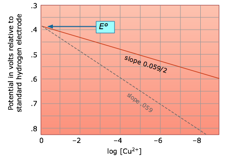
change. Thus for the dissolution of metallic copper
The
Nernst equation tells us that a half-cell potential will change by 59
millivolts per 10-fold change in the concentration of a substance
involved in a one-electron oxidation or reduction; for two-electron
processes, the variation will be 28 millivolts per decade concentration
change. Thus for the dissolution of metallic copper
 The equation just above for the Cu/Cu2+ half-cell raises an interesting question: suppose you immerse a piece of copper in a solution of pure water. With Q = [Cu2+]
= 0, the potential difference between the electrode and the solution
should be infinite! Are you in danger of being electrocuted? You need
not worry; without any electron transfer, there is no charge to zap you
with. Of course it won't be very long before some Cu2+ ions
appear in the solution, and if there are only a few such ions per liter,
the potential reduces to only about 20 volts. More to the point,
however, the system is so far from equilibrium (for example, there are
not enough ions to populate the electric double layer) that the Nernst
equation doesn't really give meaningful results. Such an electrode is
said to be unpoised.
What ionic concentration is needed to poise an electrode? I don't
really know, but I would be suspicious of anything much below 10–6 M.
The equation just above for the Cu/Cu2+ half-cell raises an interesting question: suppose you immerse a piece of copper in a solution of pure water. With Q = [Cu2+]
= 0, the potential difference between the electrode and the solution
should be infinite! Are you in danger of being electrocuted? You need
not worry; without any electron transfer, there is no charge to zap you
with. Of course it won't be very long before some Cu2+ ions
appear in the solution, and if there are only a few such ions per liter,
the potential reduces to only about 20 volts. More to the point,
however, the system is so far from equilibrium (for example, there are
not enough ions to populate the electric double layer) that the Nernst
equation doesn't really give meaningful results. Such an electrode is
said to be unpoised.
What ionic concentration is needed to poise an electrode? I don't
really know, but I would be suspicious of anything much below 10–6 M.
It is frequently useful to look at the situation in another way by considering what combinations of potential and pH allow the stable existence of a particular species. This information is most usefully expressed by means of a E-vs.-pH diagram, also known as a Pourbaix diagram.
 which, at 25°C and unit H2 partial pressure reduces to
 which similarly becomes E = 1.23 – 0.059 pH, so the E-vs-pH plots for both processes have identical slopes and yield the stability diagram for water shown below.
The above diagram has special relevance to electrochemical corrosion
of metals. Thus metals above hydrogen in the activity series will tend
to undergo oxidation (corrosion) by reducing H+ ions or water.
The driving force for this process is the free energy change ΔG associated with the concentration gradient (C2 – C1), sometimes known as the free energy of dilution:
The Nernst equation for this cell is
E = E° - (0.059/N) log Q = 0 - 0.29 log 0.1 = +0.285 v
The presence of oxygen in the atmosphere has a profound effect on the redox properties of the aquatic environment— that is, on natural waters exposed directly or indirectly to the atmosphere, and by extension, on organisms that live in an aerobic environment.This is due, of course, to its being an exceptionally strong oxidizing agent and thus a low-lying sink for electrons from most of the elements and all organic compounds.
To get an idea of its significance, consider the following chart that shows the pE° values of some redox systems that are of immense importance in the aquatic environment.
You may recall the phenomena of osmosis and osmotic pressure that are observed when two solutions having different solute concentrations are separated by a thin film or membrane whose porosity allows small ions and molecules to diffuse through, but which holds back larger particles. If one solution contains a pair of oppositely-charged ionic species whose sizes are very different, the smaller ions may pass through the semipermeable membrane while the larger ones are retained. This will produce a charge imbalance between the two solutions, with the original solution having the charge sign of the larger ion. Eventually the electrical work required to bring about further separation of charges becomes too large to allow any further net diffusion to take place, and the system settles into an equilibrium state in which a constant potential difference (usually around a volt or less) is maintained. This potential difference is usually called a membrane potential or Donnan potential after the English chemist who first described this phenomenon around 1930.
The figure shows a simple system containing the potassium salt
of a protein on one side of a membrane, and potassium chloride on the
other. The proteinate anion, being too large to diffuse through the
membrane, gives rise to the potential difference. The value of this
potential difference can be expressed by a relation that is essentially
the same as the Nernst equation, although its derivation is different.
The membrane potential can be expressed in terms of the ratio of either
the K+ or Cl– ion activities:
 The membrane surrounding most living cells contains sites or "channels" through which K+ ions are selectively transported so that the concentration of K+
inside the cell is 10-30 times that of the intracellular fluid. Taking
the activity ratio as about 20, the above equation predicts that the
potential difference θinside - θoutside will be
The membrane surrounding most living cells contains sites or "channels" through which K+ ions are selectively transported so that the concentration of K+
inside the cell is 10-30 times that of the intracellular fluid. Taking
the activity ratio as about 20, the above equation predicts that the
potential difference θinside - θoutside will be
 which is consistent with observed values. Transport of an ion such as K+
from a region of low concentration into the more concentrated
intercellular fluid requires a source of free energy, which is supplied
by ATP under enzymatic control. The metabolic processes governing this
action are often referred to as "ion pumps".
which is consistent with observed values. Transport of an ion such as K+
from a region of low concentration into the more concentrated
intercellular fluid requires a source of free energy, which is supplied
by ATP under enzymatic control. The metabolic processes governing this
action are often referred to as "ion pumps".
Latimer diagrams
Considerable insight into the chemistry of a single
element can be had by comparing the standard electrode potentials (and
thus the relative free energies) of the various oxidation states of the
element. The most convenient means of doing this is the Latimer diagram. As an example, consider the Latimer diagram for iron:The more positive the reduction potential, the greater will be the tendency of the species on the left to be reduced to the one on the right. To see how Latimer diagrams are used, look first at the one for iron in acid solution. The line connecting Fe3+ and Fe2+ represents the reaction
Fe3+ + e– → Fe2+
whose positive E° (.440 v) indicates that metallic iron will dissolve in acidic solution to form Fe2+.
Because the oxidation of this species to the +3 state has a negative
potential (-.771v; moving to the left on the diagram reverses the sign),
the +2 state will be the stable oxidation state of iron under these
conditions.Disproportionation
This Latimer diagram for chlorine illustrates an important principle:Behavior of chlorine in water
Cl2 can oxidize water (green
arrows, top) and also undergo disproportionation (purple arrows,
bottom). In the latter process, one Cl2 molecule donates electrons to another.
Thermodynamics of galvanic cells
The free energy change for a process represents the maximum amount of non-PV
work that can be extracted from it. In the case of an electrochemical
cell, this work is due to the flow of electrons through the potential
difference between the two electrodes. Note, however, that as the rate
of electron flow (i.e., the current) increases, the potential difference
must decrease; if we short-circuit the cell by connecting the two
electrodes with a conductor having negligible resistance, the potential
difference is zero and no work will be done. The full amount of work can
be realized only if the cell operates at an infinitesimal rate; that
is, reversibly.The total amount of energy a reaction can supply under standard conditions at constant pressure and temperature is given by ΔH°. If the reaction takes place by combining the reactants directly (no cell) or in a short-circuited cell, no work is done and the heat released is ΔH. If the reaction takes place in a cell that performs electrical work, then the heat released is diminished by the amount of electrical work done. In the limit of reversible operation, the heat released becomesYou should recall that this is exactly analogous to the expansion of an ideal gas. The full amount of work w = PdV is extracted only under the special condition that the external pressure P opposing expansion is only infinitesimally smaller than the pressure of the gas itself. If the gas is allowed to expand into a vacuum (P = 0), no work will be done.
ΔH = ΔG° + T ΔS
What you need to know
Make sure you thoroughly understand the following
essential ideas which have been presented above. It is especially
important that you know the precise meanings of all the highlighted
terms in the context of this topic.- When we refer to the "standard potential of a half-cell" or "couple" M2+/M, we mean the potential difference Eright – Eleft of the cell
Pt | H2(g) | H+ || M2+ (aq) | M(s)whose left half consists of a standard hydrogen electrode (SHE) and whose net reaction is
H2(g) + M2+(aq) → 2H+ + M(s)
- If the potential difference of this cell is positive (Eright – Eleft >0), electrons will flow through an external circuit from the Pt/H2 electrode to the M electrode and the cell reaction will spontaneously proceed in the direction written. The more positive the cell potential, the greater the tendency of this reaction to occur and the stronger the oxidizing agent M2+.
- Through the relation E° = – ΔG°/nF it is apparent that a standard half-cell reduction potential is simply the decrease in the free energy per mole of electrons transferred to H+ ions under the conditions that define the SHE. Strong reducing agents (good electron donors) have more negative E°s, while strong oxidizing agents (good acceptors) have more positive E°s.
- For a more general cell X(s) | X+ || M2+ | M(s) , E° is similarly the fall in free energy per electron-mole when M2+ is reduced by X. This reaction can proceed spontaneously only if the cell potential is positive (ΔG° negative.)
- An electron free energy diagram that displays various redox couples on a vertical scale of free energies relative to H+ serves as a convenient means of visualizing the possible reactions when two or more redox-active pairs are present in a solution. The position of a redox couple in relation to those of the H2/ H+ and H2O/O2,H+ couples is especially significant because it indicates whether a given species will be thermodynamically stable in water.
- Latimer diagrams provide a convenient means of correlating the various oxidation states of a particular element.
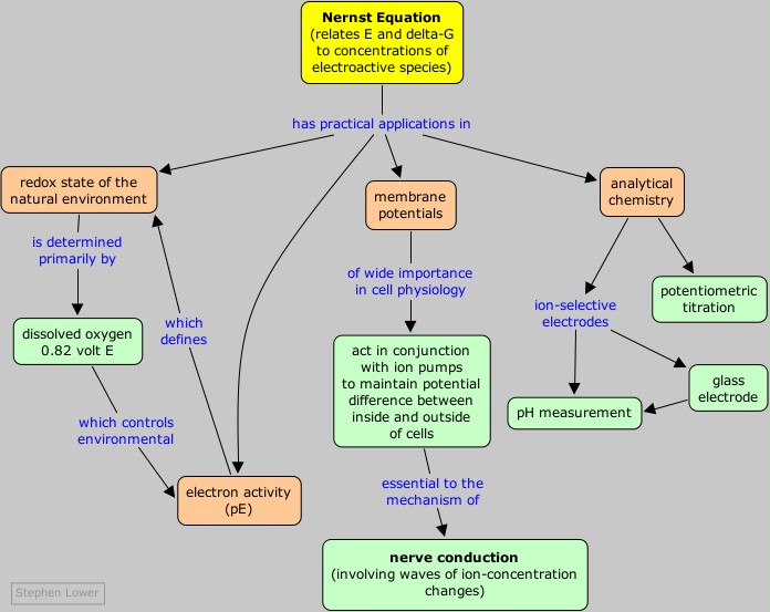
Concept Map
How cell potentials depend on concentrations
The standard cell potentials we discussed in a previous section refer to cells in which all dissolved substances are at unit activity,
which essentially means an "effective concentration" of 1M. Similarly,
any gases that take part in an electrode reaction are at an effective
pressure (known as the fugacity) of 1 atm. If these
concentrations or pressures have other values, the cell potential will
change in a manner that can be predicted from the principles you already
know.Suppose, for example, that we reduce the concentration of Zn2+ in the Zn/Cu cell from its standard effective value of 1M to an to a much smaller value:
Zn(s) | Zn2+(aq, .001M) || Cu2+(aq) | Cu(s)
This will reduce the value of Q for the cell reaction
Zn(s) + Cu2+ → Zn2+ + Cu(s)
thus making it more spontaneous, or "driving it to the right" as the Le Châtelier principle would predict, and making its free energy change ΔG more negative than ΔG°, so that E would be more positive than E°.The relation between the actual cell potential E and the standard potential E° is developed in the following way. We begin with the equation derived previously which relates the standard free energy change (for the complete conversion of products into reactants) to the standard potential
ΔG° = –nFE°
By analogy we can write the more general equation
ΔG = –nFE
which expresses the change in free energy for any extent of
reaction— that is, for any value of the reaction quotient Q. We now
substitute these into the expression that relates ΔG and ΔG° which you will recall from the chapter on chemical equilibrium:
ΔG = ΔG° + RT ln Q
which gives
–nFE = –nFE° + RT ln Q
which can be rearranged to |
(1)
|
 |
(2)
|
Significance of the Nernst eqation
The
Nernst equation tells us that a half-cell potential will change by 59
millivolts per 10-fold change in the concentration of a substance
involved in a one-electron oxidation or reduction; for two-electron
processes, the variation will be 28 millivolts per decade concentration
change. Thus for the dissolution of metallic copper
Cu(s) → Cu2+ + 2e–
the potential
E = (– 0.337) – .0295 log [Cu2+]
becomes more positive (the reaction has a greater tendency
to take place) as the cupric ion concentration decreases. This, of
course, is exactly what the Le Châtelier Principle predicts; the more dilute the product, the greater the extent of the reaction. Electrodes with poise
The equation just above for the Cu/Cu2+ half-cell raises an interesting question: suppose you immerse a piece of copper in a solution of pure water. With Q = [Cu2+]
= 0, the potential difference between the electrode and the solution
should be infinite! Are you in danger of being electrocuted? You need
not worry; without any electron transfer, there is no charge to zap you
with. Of course it won't be very long before some Cu2+ ions
appear in the solution, and if there are only a few such ions per liter,
the potential reduces to only about 20 volts. More to the point,
however, the system is so far from equilibrium (for example, there are
not enough ions to populate the electric double layer) that the Nernst
equation doesn't really give meaningful results. Such an electrode is
said to be unpoised.
What ionic concentration is needed to poise an electrode? I don't
really know, but I would be suspicious of anything much below 10–6 M.The Nernst equation works only in dilute ionic solutions
Ions of opposite charge tend to associate into loosely-bound ion pairs in more concentrated solutions, thus reducing the number of ions that are free to donate or accept electrons at an electrode. For this reason, the Nernst equation cannot accurately predict half-cell potentials for solutions in which the total ionic concentration exceeds about 10–3 M.
How the cell potential really depends on concentration!
The Nernst equation accurately predicts cell potentials only when the equilibrium quotient term Q is expressed in activities. Ionic activities depart increasingly from concentrations when the latter exceed 10–4 to 10–5 M, depending on the sizes and charges of the ions. |
 |
Activities and activity coefficients
If the Nernst equation is applied to more concentrated solutions, the terms in the reaction quotient Q must be expressed in "effective concentrations" or activities of the electroactive ionic species. The activity coefficient γ (gamma) relates the concentration of an ion to its activity a in a given solution through the relation a = γc. Since electrode potentials measure activities directly, activity coefficients can be determined by carrying out appropriate EMF measurements on cells in which the concentration of the ion of interest is known. The resulting Es can then be used to convert concentrations into activities for use in other calculations involving equilibrium constants.
Cell potentials and pH: stability diagrams
As most of us recall from our struggles with balancing redox
equations in beginning chemistry courses, many electron-transfer
reactions involve hydrogen ions and hydroxide ions. The standard
potentials for these reactions therefore refer to the pH, either 0 or
14, at which the appropriate ion has unit activity. Because multiple
numbers of H+ or OH– ions are often involved, the potentials given by the Nernst equation can vary greatly with the pH.It is frequently useful to look at the situation in another way by considering what combinations of potential and pH allow the stable existence of a particular species. This information is most usefully expressed by means of a E-vs.-pH diagram, also known as a Pourbaix diagram.
Stability of water
As was noted in connection with the shaded region in the figure below, water is subject to decomposition by strong oxidizing agents such as Cl2 and by reducing agents stronger than H2. The reduction reaction can be written either as
2H+ + 2e– → H2(g)
or, in neutral or alkaline solutions as
H2O + 2 e– → H2(g) + 2 OH–
These two reactions are equivalent and follow the same Nernst equation
E = E° - (.059/2) × 2 pH = –0.059 pH
Similarly, the oxidation of water
H2O → O2(g) + 4 H+ + 2 e–
is governed by the Nernst equation |
Stability (Pourbaix) diagram for water
The two E° values shown at the left refer to "standard" conditions of unit H+ activity (pH=0) and gas pressures of 1 atm. At combinations of pH and E that lie outside the shaded area, the partial pressures of O2 or H2
exceed 1 atm, signifying the decomposition of water. The unity partial
pressures are of course arbitrary criteria; in a system open to the
atmosphere, water can decompose even at much lower H2 partial pressures, and at oxygen pressures below 0.2 atm. Fortunately, these processes are in most cases quite slow. |
Chlorine in water
Because chlorine is widely used as a disinfectant for drinking water, swimming pools, and sewage treatment, it is worth looking at its stability diagram. Note that the effective bactericidal agent is not Cl2 itself, but its oxidation product hypochlorous acid HOCl which predominates at pH values below its pKa of 7.3. Note also that-
Cl2 is unstable in water except at very low pH; it decomposes into HOCl and Cl–.
-
Hypochlorous acid and its anion are stronger oxidants than O2 and thus subject to decomposition in water. The only stable chlorine species in water is Cl–.
-
Decomposition of HOCl occurs very slowly in the dark,
but is catalyzed by sunlight. For this reason the chlorine in outside
swimming pools must be frequently renewed.
-
Decomposition of Cl2 and HOCl by reaction
with organic material in municipal water supply systems sometimes makes
it necessary to inject additional chlorine at outlying locations.
 |
Stability diagram for chlorine in water
Each solid line represents a combination of E and pH at
which the two species on either side of it can coexist; at all other
points, only a single species is stable. Note that equilibria between
species separated by diagonal lines are dependent on both E and pH, while those separated by horizontal or vertical lines are affected by pH only or E only, respectively. |
Iron
Stability diagrams are able to condense a great amount of information into a compact representation, and are widely employed in geochemistry and corrosion engineering. The Pourbaix diagram for iron is one of the more commonly seen examples.
Pourbaix diagram for iron
Three oxidation states of iron (0, +2 and +3) are represented on this diagram. The stability regions for the oxidized iron states are shown only within the stability region of H2O. Equilibria between species separated by vertical lines are dependent on pH only. The +3 oxidation state is the only stable one in environments in which the oxidation level is controlled by atmospheric O2. This is the reason the Earth’s crust contains iron oxides, which developed only after the appearance of green plants which are the source of O2. Iron is attacked by H+ to form H2 and Fe(II); the latter then reacts with O2 to form the various colored Fe(III) oxides that constitute “rust”. Numerous other species such as oxides and hydrous oxides are not shown. A really “complete” diagram for iron would need to have at least two additional dimensions showing the partial pressures of O2 and CO2. |
 |
Concentration cells
From your study of thermodynamics you may recall that the process
solute (concentrated) → solute (dilute)
is accompanied by a fall in free energy, and therefore is
capable of doing work on the surroundings; all that is required is some
practical way of capturing this work. One way of doing this is by means
of a concentration cell such as
Cu(s) | CuNO3(.1 M) || CuNO3(.01 M) | Cu(s)
cathode: Cu2+(.1 M) + 2e– → Cu(s)
anode: Cu(s) → Cu2+(.01 M) + 2e–
net: Cu2+(.1 M) → Cu2+(.01 M)
which represents the transport of cupric ion from a region of higher concentration to one of lower concentration.The driving force for this process is the free energy change ΔG associated with the concentration gradient (C2 – C1), sometimes known as the free energy of dilution:
ΔGdilution = RT ln(C2 – C1)
Note, however, that Cu2+ ions need not physically
move between the two compartments; electron flow through the external
circuit creates a "virtual" flow as copper ions are created in the
low-concentration side and discharged at the opposite electrode. Nitrate
ions must also pass between the cells to maintain electroneutrality.The Nernst equation for this cell is
E = E° - (0.059/N) log Q = 0 - 0.29 log 0.1 = +0.285 v
Note that E° for a concentration cell is
always zero, since this would be the potential of a cell in which the
electroactive species are at unit activity in both compartments.
What you need to know
Make sure you thoroughly understand the following essential ideas
which have been presented above. It is especially imortant that you
know the precise meanings of all the highlighted terms in the context of
this topic.- The Nernst equation relates the effective concentrations (activities) of the components of a cell reaction to the standard cell potential. For a simple reduction of the form Mn+ + ne– → M, it tells us that a half-cell potential will change by 59/n millivolts per 10-fold change in the activity of the ion.
- Ionic concentrations can usually be used in place of activities when the total concentration of ions in the solution does not exceed about about 0.001M.
- In those reactions in which H+ or OH– ions take part, the cell potential will also depend on the pH. Plots of E vs. pH showing the stability regions of related species are very useful means of summarizing the redox chemistry of an element.
Concept Map
Oxygen and the aquatic environment
We ordinarily think of the oxidation potential being
controlled by the concentrations of the oxidized and reduced forms of a
redox couple, as given by the Nernst equation. Under certain
circumstances it becomes more useful to think of E as an independent variable that can be used to control the value of Q
in the Nernst equation. This usually occurs when two redox systems are
present, one being much more concentrated or kinetically active than the
other. By far the most important example of this is the way atmospheric
oxygen governs the composition of the many redox systems connected with
biological activity. The presence of oxygen in the atmosphere has a profound effect on the redox properties of the aquatic environment— that is, on natural waters exposed directly or indirectly to the atmosphere, and by extension, on organisms that live in an aerobic environment.This is due, of course, to its being an exceptionally strong oxidizing agent and thus a low-lying sink for electrons from most of the elements and all organic compounds.
Those parts of the environment that are protected from atmospheric oxygen are equally important because it is only here that electrons are sufficiently available to produce the "reducing" conditions that are essential for processes varying from photosynthesis to nitrogen fixation.
Problem Example
(a) Estimate the redox potential of a natural water that is in equilibrium with the atmosphere at pH 7 and 298K.
(b) What fraction of a dilute solution Fe2+ will be in its oxidized form Fe3+ in such a water?
Solution: The relevant E°s are 1.23 v for O2(g) + 4H+ + 4e–→ 2H2O and .77 v for the Fe3+/Fe2+ couple.
(a) The potential (with respect to the SHE, of course) is given by the Nernst equation
 which works out to E = 0.82 volt. As the LeChâtelier principle predicts, the higher pH (lower [H+] compared to that at the "standard" pH of zero) reduces the electron-accepting tendency of oxygen.
(b) The Nernst equation for the reduction of Fe3+ is E = .77–.059 log Q, in which Q is the ratio [Fe2+]/[Fe3+]. With E set by the O2/H2O couple, this becomes
(b) What fraction of a dilute solution Fe2+ will be in its oxidized form Fe3+ in such a water?
Solution: The relevant E°s are 1.23 v for O2(g) + 4H+ + 4e–→ 2H2O and .77 v for the Fe3+/Fe2+ couple.
(a) The potential (with respect to the SHE, of course) is given by the Nernst equation
(b) The Nernst equation for the reduction of Fe3+ is E = .77–.059 log Q, in which Q is the ratio [Fe2+]/[Fe3+]. With E set by the O2/H2O couple, this becomes
0.82 = .77 – .059 log Q
which gives Q = 10–0.85 or [Fe2+]/[Fe3+] = 0.14/1, so the fraction of the iron in its oxidized form is 1/1.14 = 0.88.If we can have pH, why not pE?
As you will recall from your study of acid-base chemistry, the pH of a solution (defined as –log {H+}) is a measure of availablity (technically, the activity) of protons in the solution. As is explained in more detail here, protons tend to "fall" (in free energy) from filled donor levels (acids) to lower acceptor levels (bases.) Through the relation
[H+] ≈ Ka(Ca/Cb)
which can be rewritten as
(Ca/Cb) ≈ [H+]/Ka
in which the pH is treated as an independent variable that
controls the ratio of the conjugate forms of any acid-base pairs in the
solution:
log (Ca/Cb) ≈ pH – pKa
In the same way, we can define the pE as the negative log of the electron activity in the solution:
pE = –log{e–}
Electrons, of course, cannot exist as independent particles in
aqueous solution, but neither can protons for that matter! It is
nevertheless quite valid to refer to the activities of these
particles (but not to their "concentrations") when we are considering
their availability to donors and acceptors. We will not get into the
details of how pE is actually calculated (it is of course related to the
ordinary standard electrode potential.)To get an idea of its significance, consider the following chart that shows the pE° values of some redox systems that are of immense importance in the aquatic environment.
 |
Environmentally-important redox systems
|
A few other points about this plot are worth noting:
The standard potential for the net reaction refers to a
hypothetical solution in which the activities of the two ions are unity.
The cell potential we actually observe corresponds to E in the Nernst equation, which is then solved for Q which gives Ksp directly.
 which causes the potential to rise as more iron becomes oxidized.
When the equivalence point is reached, the Fe2+ will have been totally consumed (the large equilibrium constant ensures that this will be so), and the potential will then be controlled by the concentration ratio of Ce3+/Ce4+. The idea is that both species of a redox couple must be present in reasonable concentrations poise an electrode (that is, to control its potential according to the Nernst equation.) If one works out the actual cell potentials for various concentrations of all these species, the resulting titration curve looks much like the familiar acid-base titration curve. The end point is found not by measuring a particular cell voltage, but by finding what volume of titrant gives the steepest part of the curve.
 Since pH is actually defined in terms of hydrogen ion activity and not its concentration, a hydrogen electrode allows a direct measure of {H+} and thus of –log {H+}, which is the pH. All you need is to measure the voltage of a cell
 The potential of a glass electrode is given by a form of the
Nernst equation very similar to that of an ordinary hydrogen electrode,
but of course without the H2:
The potential of a glass electrode is given by a form of the
Nernst equation very similar to that of an ordinary hydrogen electrode,
but of course without the H2:
The reason a glass membrane would behave in this way was not understood until around 1970. It now appears that hydrogen ions in the external solution diffuse through the glass and push out a corresponding number of the Na+ ions which are normally present in most glasses. These sodium ions diffuse to whichever side of the membrane has the lower concentration, where they remain mostly confined to the surface of the glass, which has a porous, gelatinous nature. It is the excess charge produced by these positive ions that gives rise to the pH-dependent potential.
- Anaerobic organisms must make do with electron-acceptors above oxygen. The poor bacteria that depend on reducing hydrogen ions (2) have it worst of all, gaining only a tiny amount of metabolic energy to produce a tiny puff of hydrogen gas.
- Reaction (3) is not much more efficient, but it is the vital first link in the process of natural nitrogen fixation that gets carried out in the protected electron-rich environment of the organisms that live in the root nodules of legumes.
- The consequences of (4) are readily apparent if you have ever noticed the rotten-egg odor of some poorly-aerated muddy soils.
- Reaction (6) is known as fermentation; it takes place in the anarobic soils of marshes and bogs (hence the nickname "marsh gas" for methane) and in the insides of animals from termites to cows, and sometimes to our embarrassment, in ourselves. Notice that glucose plays the double role of electron donor and acceptor here; this is a disproportionation reaction.
- Finally, if you have ever had much to do with
babys' diapers, you have likely noticed the smell of ammonia produced as
the anaerobic bacteria from within deliver electrons to nitrate ions (7).
It's important to bear in mind that the reactions discussed above are mediated by living organisms; without the necessary enzymes to catalyze them, their rates are essentially zero.
For a more detailed chart, see Falling through the respiratory chain.
Analytical chemistry applications
A very large part of Chemistry is concerned, either directly or
indirectly, with determining the concentrations of ions in solution.
Any method that can accomplish such measurements using relatively simple
physical techniques is bound to be widely exploited. Cell potentials
are fairly easy to measure, and although the Nernst equation relates
them to ionic activities rather than to concentrations, the difference
between them becomes negligible in solutions where the total ionic
concentration is less than about 10–3 M.Determination of solubility products
The concentrations of ions in equilibrium with a sparingly soluble salt are sufficiently low that their direct determination can be quite difficult. A far simpler and common procedure is to set up a cell in which one of the electrode reactions involves the insoluble salt, and whose net cell reaction corresonds to the dissolution of the salt. For example, to determine the Ksp for silver chloride, we could use the cell
Ag(s) | Ag+(? M) || Ag+,Cl– | AgCl(s) | Ag(s)
whose net equation corresponds to the dissolution of silver chloride:
cathode:
|
AgCl(s) + e– → Ag(s) + Cl–(aq) | E° = +.222 v |
anode:
|
Ag(s) → Ag+(aq) + e– | E° = –(+.799) v |
net:
|
AgCl(s) → Ag+ + Cl– | E° = -.577 v |
Potentiometric titrations
In many situations, accurate determination of an ion concentration by direct measurement of a cell potential is impossible due to the presence of other ions and a lack of information about activity coefficients. In such cases it is often possible to determine the ion indirectly by titration with some other ion. For example, the initial concentration of an ion such as Fe2+ can be found by titrating with a strong oxidizing agent such as Ce4+. The titration is carried out in one side of a cell whose other half is a reference electrode:
Pt(s) | Fe2+, Fe3+ || reference electrode
Initially the left cell contains only Fe2+. As the titrant is added, the ferrous ion is oxidized to Fe3+ in a reaction that is virtually complete:
Fe2+ + Ce4+ → Fe3+ + Ce3+
The cell potential is followed as the Fe2+ is added
in small increments. Once the first drop of ceric ion titrant has been
added, the potential of the left cell is controlled by the ratio of
oxidized and reduced iron according to the Nernst equationWhen the equivalence point is reached, the Fe2+ will have been totally consumed (the large equilibrium constant ensures that this will be so), and the potential will then be controlled by the concentration ratio of Ce3+/Ce4+. The idea is that both species of a redox couple must be present in reasonable concentrations poise an electrode (that is, to control its potential according to the Nernst equation.) If one works out the actual cell potentials for various concentrations of all these species, the resulting titration curve looks much like the familiar acid-base titration curve. The end point is found not by measuring a particular cell voltage, but by finding what volume of titrant gives the steepest part of the curve.
Measurement of pH
Since pH is actually defined in terms of hydrogen ion activity and not its concentration, a hydrogen electrode allows a direct measure of {H+} and thus of –log {H+}, which is the pH. All you need is to measure the voltage of a cell
H2(g, 1 atm) | Pt | H+(? M) || reference electrode
In theory this is quite simple, but when it was first employed
in the pre-electronics era, it required some rather formidable-looking
apparatus (such as the L&N vibrating-reed electrometer setup from
the 1920's shown here) and the use of explosive hydrogen gas. Although
this arrangement (in which the reference electrode could be a standard
hydrogen electrode) has been used for high-precision determinations
since that time, it would be impractical for routine pH measurements of
the kinds that are widely done, especially outside the research
laboratory.The glass electrode for pH measurements
In 1914 it was discovered that a thin glass membrane enclosing a solution of HCl can produce a potential that varies with the hydrogen ion activity {H+} in about the same way as that of the hydrogen electrode. Glass electrodes are manufactured in huge numbers for both laboratory and field measurements. They contain a built-in Ag-AgCl reference electrode in contact with the HCl solution enclosed by the membrane.
Emembrane = A + (RT/F) ln ( {H+} + B )
in which A and B are constants that depend on the particular glass membrane. The reason a glass membrane would behave in this way was not understood until around 1970. It now appears that hydrogen ions in the external solution diffuse through the glass and push out a corresponding number of the Na+ ions which are normally present in most glasses. These sodium ions diffuse to whichever side of the membrane has the lower concentration, where they remain mostly confined to the surface of the glass, which has a porous, gelatinous nature. It is the excess charge produced by these positive ions that gives rise to the pH-dependent potential.
The first commercial pH meter was developed by Arnold Beckman (1900-2004) while he was a Chemistry professor at CalTech. He was unable to interest any of the instrumentation companies in marketing it, so he founded his own company and eventually became a multi-millionaire philanthropist.
 |
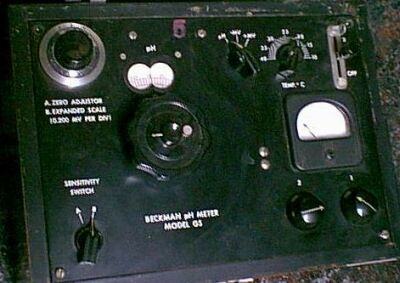 |
 |
Arnold Beckman
|
An early Beckman pH meter
|
A typical modern pH meter
|
Ion-selective electrodes
The function of the membrane in the glass electrode is to allow hydrogen ions to pass through and thus change its potential, while preventing other cations from doing the same thing (this selectivity is never perfect; most glass electrodes will respond to moderate concentrations of sodium ions, and to high concentrations of some others.) A glass electrode is thus one form of ion-selective electrode. Since about 1970, various other membranes have been developed which show similar selectivities to certain other ions. These are widely used in industrial, biochemical, and environmental applications.
A comprehensive Beginners Guide to ion-selective electrodes
Membrane potentials and nerve conduction
You may recall the phenomena of osmosis and osmotic pressure that are observed when two solutions having different solute concentrations are separated by a thin film or membrane whose porosity allows small ions and molecules to diffuse through, but which holds back larger particles. If one solution contains a pair of oppositely-charged ionic species whose sizes are very different, the smaller ions may pass through the semipermeable membrane while the larger ones are retained. This will produce a charge imbalance between the two solutions, with the original solution having the charge sign of the larger ion. Eventually the electrical work required to bring about further separation of charges becomes too large to allow any further net diffusion to take place, and the system settles into an equilibrium state in which a constant potential difference (usually around a volt or less) is maintained. This potential difference is usually called a membrane potential or Donnan potential after the English chemist who first described this phenomenon around 1930.
Origin of a membrane potential
If the smaller ions are able to diffuse through the
membrane but the larger ions cannot, a potential difference will develop
between the two solutions. This membrane potential can be observed by
introducing a pair of platinum electrodes. |
 |
See this site for nice simulations of some of these effects with good explanatory material. (Look under "Diffusion Potentials".)
Nerve conduction
Transmission of signals through the nervous system occurs not by the movement of a charge carrier through the nerve, but by waves of differential ion concentrations that travel along the length of the nerve. These concentration gradients are reduced by protein-based ion channels and ATP-activated (and energy-consuming) ion pumps specific to K+ and Ca2+ ions.
Conduction of nerve impulses
We sometimes think of our nerves as the
body's wiring, but the "electricity" that they transmit is not a flow of
electrons, but a rapidly-traveling wave of depolarization involving the
transport of ions through the nerve membrane. The normal potential
difference between the inner and outer parts of nerve cells is about –70
mv as estimated above. Transmissin of a nerve impulse is initiated by a
reduction of this potential difference to about –20 mv. This has the
effect of temporarily opening the Na+ channel; the influx of
these ions causes the membrane potential of the adjacent portion of the
nerve to collapse, leading to an effect that is transmitted along the
length of the nerve. As this pulse passes, K+ and Na+ pumps restore the nerve to its resting condition.
|
 |
Transport of ions across cell membranes - nice animations!
What you need to know
Make sure you thoroughly understand the following essential ideas
which have been presented above. It is especially imortant that you
know the precise meanings of all the highlighted terms in the context of
this topic.- Atmospheric oxygen is a strong oxidizing agent, but in the absence of a suitable catalyst this reaction is ordinarily too slow to be observable. In organisms that possess the appropriate enzymes, the reaction is sufficiently fast to control the availability of electrons to other redox systems.
- The pE is a useful index of electron availability, expecially in natural waters and biological systems in which multiple redox systems are usually present. Although electrons tend to "fall" (in free energy) from sources to sinks, the outcome depends very strongly on the rates of the various reactions. This is quite different from proton-exchange (acid-base) reactions which are uniformly fast.
- Solubility products can often be measured by constructing a cell in which one of the electrodes involves the sparingly soluble salt, and the net cell equation corresponds to the solubility reaction.
- Potentiometric titrations are widely used to measure concentrations of species that are readily oxidized or reduced. The reaction must be fast and have a very large equilibrium constant. The equivalance point is detected by the rapid change in potential that occurs when control of the cell potential passes from the redox system of the analyte to that of the titrant.
- Measurement of pH is accomplished with an electrode consisting of a thin membrane of glass in which Na+ ions are exchanged with H+.
- Membrane (Donnan) potentials arise when passage of an ion across a semipermeable membrane is selectively facilitated or inhibited. The classic example is a sodium proteinate solution in which the protein anion is too large to pass through the membrane. In organisms, ion-specific channels or "pumps" have a similar effect.
- Nerve conduction occurs not by a flow of charge through the nerve, but by a wave of depolarization resulting from the concerted action of active channels that govern the passage of ions (mainly K+ and Na+) across the membrane enclosing the nerve.
Concept Map
One of the oldest and most important applications of electrochemistry
is to the storage and conversion of energy. You already know that a galvanic cell converts chemical energy to work; similarly, an electrolytic cell converts electrical work into chemical free energy. Devices that carry out these conversions are called batteries.
In ordinary batteries the chemical components are contained within the
device itself. If the reactants are supplied from an external source as
they are consumed, the device is called a fuel cell.
The technology of lead-acid storage batteries has undergone remarkably little change since the late 19th century. Their main drawback as power sources for electric vehicles is the weight of the lead; the maximum energy density is only about 35 Ah/kg, and actual values may be only half as much. There are also a few other problems:
 Despite its name, this cell is not really "dry"; the electrolyte is a wet paste containing NH4Cl
to supply the hydrogen ions. The chemistry of this cell is more
complicated than it would appear from these equations, and there are
many side reactions and these cells have limited shelf-lifes due to self
discharge. (In some of the older ones, attack by the acidic ammonium
ion on the zinc would release hydrogen gas, causing the battery to swell
and rupture, often ruining an unused flashlight or other device.) A
more modern version, introduced in 1949, is the alkaline cell
which employs a KOH electrolyte and a zinc-powder anode which permits
the cell to deliver higher currents and avoids the corrosive effects of
the acidic ammonium ion on the zinc.
Despite its name, this cell is not really "dry"; the electrolyte is a wet paste containing NH4Cl
to supply the hydrogen ions. The chemistry of this cell is more
complicated than it would appear from these equations, and there are
many side reactions and these cells have limited shelf-lifes due to self
discharge. (In some of the older ones, attack by the acidic ammonium
ion on the zinc would release hydrogen gas, causing the battery to swell
and rupture, often ruining an unused flashlight or other device.) A
more modern version, introduced in 1949, is the alkaline cell
which employs a KOH electrolyte and a zinc-powder anode which permits
the cell to deliver higher currents and avoids the corrosive effects of
the acidic ammonium ion on the zinc.
See here for some interesting pictures of very early electrochemistry cells.
The term battery derives from the older use of this word to describe physical attack or "beating"; Benjamin Franklin first applied the term to the electrical shocks that could be produced by an array of charged glass plates. In common usage, the term "call" is often used in place of battery.
The ideal and the real
For portable and transportation applications especially, a battery or fuel cell should store (and be able to deliver) the maximum amount of energy at the desired rate (power level) from a device that has the smallest possible weight and volume. The following parameters are commonly used to express these attributes:- Storage capacity or charge density, coulombs/liter or coulombs/kg;
- Energy density, J/kg or watt-hour/lb
- Power density, watts/kg
- Voltage efficiency, ratio of output voltage to E°
- Lifetime: shelf-life (resistance to self-discharge) or charge/recharge cycles
Physical limitations of battery performance
The most important of these are:- Effective surface area of the electrode. A 1-cm2 sheet of polished metal presents far less active surface than does one that contains numerous surface projections or pores. All useful batteries and fuel cells employ highly porous electrodes. Recent advances in nanotechnology are likely to greatly improve this parameter.
- Current density of electrode surface. Expressed in amperes m–2, this is essentially a measure of the catalytic ability of the electrode, that is, its ability to reduce the activation energy of the electron transfer process.
- Rate at which electroactive components can be delivered to or depart from the active electrode surface. These processes are controlled by thermal diffusion and are inhibited by the very narrow pores that are needed to produce the large active surface area.
- Side reactions and irreversible processes. The products of the discharge reaction may tend to react with the charge-storing components. Thermal diffusion can also cause self-discharge, limiting the shelf life of the battery. Recharging of some storage batteries may lead to formation of less active modifications of solid phases, thus reducing the number of charge/discharge cycles possible.
Primary and secondary batteries
A secondary or storage battery is capable of
being recharged; its electrode reactions can proceed in either
direction. During charging, electrical work is done on the cell to
provide the free energy needed to force the reaction in the
non-spontaneous direction. A primary cell, as expemplified by
an ordinary flashlight battery, cannot be recharged with any
efficiency, so the amount of energy it can deliver is limited to that
obtainable from the reactants that were placed in it at the time of
manufacture.The lead-acid storage cell
The most well-known storage cell is the lead-acid
cell, which was invented by Gaston Planté in 1859 and is still the most
widely used device of its type.
The cell is represented by
Pb(s) | PbSO4(s) | H2SO4(aq) || PbSO4(s), PbO2(s) | Pb(s)
and the net cell reaction is
Pb(s) + PbO2(s) + 2 H2SO4(aq) → 2 PbSO4(s) + 2 H2O
The reaction proceeds to the right during discharge and to the left
during charging. The state of charge can be estimated by measuring the
density of the electrolyte; sulfuric acid is about twice as dense as
water, so as the cell is discharged, the density of the electrolyte
decreases.
Lead-acid storage cell and detail of its plate construction
|
 |
The technology of lead-acid storage batteries has undergone remarkably little change since the late 19th century. Their main drawback as power sources for electric vehicles is the weight of the lead; the maximum energy density is only about 35 Ah/kg, and actual values may be only half as much. There are also a few other problems:
- The sulfuric acid electrolyte becomes quite viscous when the temperature is low, inhibiting the flow of ions between the plates and reducing the current that can be delivered. This effect is well-known to anyone who has had difficulty starting a car in cold weather.
- These batteries tend to slowly self-discharge, so a car left idle for several weeks might be unable to start.
- Over time, PbSO4 that does not get converted to PbO2 due to lack of complete discharge gradually changes to an inert form which limits the battery capacity. Also, "fast" charging causes rapid evolution of hydrogen from the water in the electrolyte; the bubbles form on the lead surface and can tear PbO2 off the positive plate. Eventually enough solid material accumulates at the bottom of the electrolyte to short-circuit the battery, leading to its permanent demise.
The LeClanché "dry cell"
The most well-known primary battery has long been the common "dry cell" that is widely used to power flashlights and similar devices. The modern dry cell is based on the one invented by Georges Leclanché in 1866. The electrode reactions are
Zn → Zn2+ + 2e–
2 MnO2 + 2H+ + 2e– → Mn2O3 + H2O
Despite its name, this cell is not really "dry"; the electrolyte is a wet paste containing NH4Cl
to supply the hydrogen ions. The chemistry of this cell is more
complicated than it would appear from these equations, and there are
many side reactions and these cells have limited shelf-lifes due to self
discharge. (In some of the older ones, attack by the acidic ammonium
ion on the zinc would release hydrogen gas, causing the battery to swell
and rupture, often ruining an unused flashlight or other device.) A
more modern version, introduced in 1949, is the alkaline cell
which employs a KOH electrolyte and a zinc-powder anode which permits
the cell to deliver higher currents and avoids the corrosive effects of
the acidic ammonium ion on the zinc.
Timeline of battery development
Although the development practical batteries largely
paralelled the expansion of electrical technology from about the
mid-19th century on, it is now thought that a very primitive kind of
battery was apparently in use more than 2000 years ago. The brief
popularity of electrically powered automobiles
in the 1920's encouraged storage battery development. The widespread
use of portable "personal" electrical devices has kept the search for
better batteries very much alive.See here for some interesting pictures of very early electrochemistry cells.
"Baghdad Battery" - 1000 BCE? |
Earthenware jars
containing an iron rod surrounded by a copper cylinder were discovered
near Baghdad in 1938. They are believed to have been used by the Parthian civilization that occupied the region about 2000 years ago as a source of electricity to plate gold onto silver. |
Allesandro Volta 1782 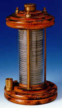 |
His "Voltaic pile", a stack of zinc and silver disks separated by a wet cloth containing a salt or a weak acid solution, was the first battery known to Western civilization. |
| Sir Humphry Davy 1813 | Davy builds a 2000-plate battery that occupies 889 square feet in the basement of Britain's Royal Society. His earlier batteries provided power for the first public demonstration of electric lighting (carbon arc). |
| Michael Faraday, 1830's | Faraday discovered the fundamentals of galvanic cells and electrolysis that put electrochemistry on a firm scientific basis. |
1836 - Daniell cell (also known as a Crow's Foot or Gravity cell.) 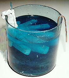 |
John Daniell (English chemist and meterologist) developed the first modern storage cell based on Faraday's principles. This consists of a large glass jar with a copper star-shaped electrode in the bottom and a zinc "crow's foot" shaped electrode suspended near the top. The bottom of the jar was filled with a concentrated copper sulfate solution. On top of this was poured dilute sulfuric acid, whose lower density kept it on top. This was the first practical battery to find wide use to power telegraphs and railway signaling systems and home doorbells. |
1839 - William Grove (Welsh) 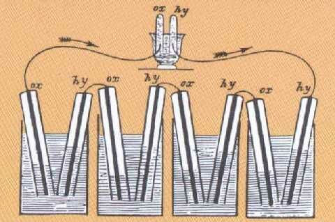 |
Grove was best known in the 19th century for his "nitric acid battery" which came into wide use in early telegraphy. |
1859 - Gaston Planté (French)  |
Invents the first lead-acid storage cell which consisted of two sheets of lead separated by a rubber sheet, rolled into a spiral and immersed in dilute sulfuric acid. |
1866 - Georges Leclanché (French)  |
By 1868 twenty thousand Leclanché cells were being used in telegraph systems. The original Leclanché cells were built in porous pots which were heavy and subject to breakage. Within twenty years other inventors had modified the design into what we now know as "dry cells" which became widely used in the first flashlights (1909) and in battery-powered radios of the 1920s. |
1881 - Faure and others 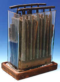 |
Development of the first practical lead-acid storage cell. The major improvement over Planté's design was the addition of a paste of PbSO4 to the positive plate. |
| 1905 Nickel-iron cell (Thomas Edison)  |
 Edison,
who was as much a chemist as an all-around inventor, thought that the
lead in Planté-type cells made them too heavy, and that having acid in
contact with any metal was an inherently bad idea. After much
experimentation, he developed a successful alkaline battery. The Edison cell
uses an iron anode, nickel oxide cathode, and KOH electrolyte. This
cell is extremely rugged and is still used in certain industrial
applications, but it was never able to displace the lead-acid cell as
Edison had hoped. Edison,
who was as much a chemist as an all-around inventor, thought that the
lead in Planté-type cells made them too heavy, and that having acid in
contact with any metal was an inherently bad idea. After much
experimentation, he developed a successful alkaline battery. The Edison cell
uses an iron anode, nickel oxide cathode, and KOH electrolyte. This
cell is extremely rugged and is still used in certain industrial
applications, but it was never able to displace the lead-acid cell as
Edison had hoped. |
| 1950s | A similar cell, employing a nickel anode instead of iron, was the first rechargeable cell that was small enough to be used in portable consumer devices. Its main disadvantage is that it is ruined by complete discharge. |
| 1949 - Alkaline dry cell - Lew Urry (Eveready Battery Co.) |
First commercial alkaline dry cell. These substitute KOH for the corrosive NH4Cl used in the older dry cells and last 5-8 times longer. |
| 1947 - Mercury cell (Ruben and Mallory, 1950's) |
This was one of the first
"button"-type cells which were widely used in cameras and hearing aids.
The constancy of the 1.34 v output made them popular for use in
sensitive instruments and cardiac pacemakers. The net cell reaction is
Zn(s) + HgO(s) → ZnO(s) + Hg(l)
Most countries have outlawed sales of these cells in order to reduce mercury contamination of the environment. |
Nickel-Cadmium (NiCad) cells  |
The NiCad cell quickly become one of the most popular rechargeable batteries for small consumer devices. They can deliver high current and undergo hundreds of charge–discharge cycles. Because cadmium is an environmental toxin, their use is being discouraged. |
| 1959 - Fuel cell - Francis Bacon (UK) | The first practical fuel cell was developed by British engineer Francis Bacon (1904-1992). This hydrogen-oxygen cell used an alkaline electrolyte and inexpensive nickel electrodes. |
Late 1960's - Nickel-metal hydride cells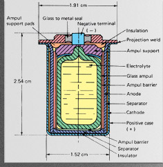 |
The hydride ion H–
would be an ideal cathode material except for the fact that its oxidation product H2 is a gas. The discovery that certain compounds such as LiNi5 and ZrNi2
can act as "hydrogen sponges" made it practical to employ metal
hydrides as a cathode material. One peculiarity of Ni-MH cells is that
recharging them is an exothermic process, so that proper dissipation of
heat must be allowed for. These batteries are widely used in cell
phones, computers, and portable power tools. The electrode reactions
take place in a concentrated KOH electrolyte:
Cathode (+): NiOOH + H2O + e–→ Ni(OH)2 + OH–
Anode (-): (1/x) MHx + OH–→ (1/x) M + H2O + e–
|
1990s - Lithium cells (Sony Corp.) 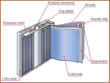 |
Lithium is an ideal anode
material owing to its low density and high reduction potential, making
Li-based cells the most compact ways of storing electrical energy.
Lithium cells are used in wristwatches, cardiac pacemakers and digital
cameras. Both primary (non-rechargeble) and rechargeable types have been
available for some time. More recent applications are in portable power
tools and— perhaps most importantly, in electric-powered or hybrid
automobiles. Modern lithium cells operate by transporting Li+ ions between electrodes into which the ions can be inserted or intercalated. Cathodes are lithium transition-metal oxides such as LiCoO3, while anodes are lithium-containing carbon, LiC6. The species that undergoes oxidation-reduction is not lithium, but the transition metal, e.g. Co(III)-Co(IV). See this Wikipedia article for a very thorough description of current lithium battery technology and for recommendation on how to store and use these cells. |
Lithium batteries as incendiary devices
There have been numerous reports of fires and explosions
associated with lithium batteries. In 2006, the Dell Corporation had to
recall 4.1 million Sony batteries that had been shipped with Dell's
laptop computers and were judged to be at risk owing to a manufacturing
defect.This illustrates the difficulty of concentrating a large amount of chemical energy into a small package, which is of course the goal of all battery developers eager to meet commercial demands ranging from consumer personal electronics to electrically-powered cars. The fully-charged Li+-deficient lithium cobalt oxide cathodes are inherently unstable, held in check only by a thin insulating membrane which, if accidentally breached, can lead to thermal runaway involving gaseous oxygen, carbon, organic solvents, and (in some cases) lithium chlorate— all the components necessary for a fierce fire.
Much research has gone into the development of fail-safe membranes. In one type, made by ExxonMobil and targeted at the automotive market, the pores are designed to close up and thus inhibit the passage of lithium ions when the temperature rises above a safe level.
Biological batteries
 Finally, we should mention the biological batteries that are found in a number of electric fish. The "electric organs" of these fish are modified muscle cells known as electrocytes
which are arranged in long stacks. A neural signal from the brain
causes all the electrocytes in a stack to become polarized
simultaneously, in effect creating a battery made of series-connected
cells. Most electric fish produce only a small voltage which they use
for navigation, much in the way that bats use sound for echo-location of
prey. The famous electric eel, however, is able to produce a 600-volt jolt that it employs to stun nearby prey.
Finally, we should mention the biological batteries that are found in a number of electric fish. The "electric organs" of these fish are modified muscle cells known as electrocytes
which are arranged in long stacks. A neural signal from the brain
causes all the electrocytes in a stack to become polarized
simultaneously, in effect creating a battery made of series-connected
cells. Most electric fish produce only a small voltage which they use
for navigation, much in the way that bats use sound for echo-location of
prey. The famous electric eel, however, is able to produce a 600-volt jolt that it employs to stun nearby prey.
The fuel cell
Conventional batteries supply electrical energy from the chemical
reactants stored within them; when these reactants are consumed, the
battery is "dead". An alternative approach would be to feed the
reactants into the cell as they are required, so as to permit the cell
to operate continuously. In this case the reactants can be thought of as
"fuel" to drive the cell, hence the term fuel cell.Although fuel cells were not employed for practical purposes until space exploration began in the 1960's, the principle was first demonstrated in 1839 by Sir William Grove, a Welsh lawyer and amateur chemist. At the time, it was already known that water could be decomposed into hydrogen and oxygen by electrolysis; Grove tried recombining the two gases in a simple apparatus, and discovered what he called "reverse electrolysis"— that is, the recombination of H2 and O2 into water— causing a potential difference to be generated between the two electrodes:
anode:
|
H2(g) → 2 H+ + 2e– | E° = 0 v |
cathode:
|
½ O2 + 2 H+ + 2e– → H2O(l) | E° = +1.23 v |
net:
|
H2(g) + ½ O2(g) → H2O(l) | E° = +1.23 v |
It was not until 1959 that the first working hydrogen-oxygen fuel cell was developed by Francis Thomas Bacon in England. Modern cells employ an alkaline electrolyte, so the electrode reactions differ from the one shown above by the addition of OH– to both sides of the equations (note that the net reaction is the same):
anode:
|
H2(g) + 2 OH– → 2 H2O + 2 e– | E° = 0 v |
cathode:
|
½ O2 (g) + 2 H2O + 2 e– → 2 OH– | E° = +1.23 v |
net:
|
H2(g) + ½ O2(g) → H2O | E° = +1.23 v |
 |
Schematic diagram of a modern
hydrogen-oxygen fuel cell. Commonly used electrolytes are NaOH solution,
phosphoric acid, or solid oxides. A major limitation of any
oxygen-consuming fuel cell is the slow rate of the reduction of this
element at a cathode. The best cathode surfaces are usually made of
platinum, which is a major cost factor in fuel cell design.
|
One reason for the interest in fuel cells is that they offer a far more efficient way of utilizing chemical energy than does conventional thermal conversion. The work obtainable in the limit of reversible operation of a fuel cell is 229 kJ per mole of H2O formed. If the hydrogen were simply burned in oxygen, the heat obtainable would be ΔH = 242 kJ mol–1, but no more than about half of this heat can be converted into work so the output would not exceed 121 kJ mol–1.
This limit is a consequence of the Second Law of Thermodynamics. The fraction of heat that can be converted into work is a function of how far (in temperature) the heat falls as it flows through the engine and into the surroundings; this fraction is given by (1 - Thigh)/Tlow. At normal environmental temperatures of around 300K, Thigh would have to be at least 600 K for 50% thermal efficiency.The major limitation of present fuel cells is that the rates of the electrode reactions, especially the one in which oxygen is reduced, tend to be very small, and thus so is the output current per unit of electrode surface. Coating the electrode with a suitable catalytic material is almost always necessary to obtain usable output currents, but good catalysts are mostly very expensive substances such as platinum, so that the resulting cells are too costly for most practical uses. There is no doubt that if an efficient, low-cost catalytic electrode surface is ever developed, the fuel cell would become a mainstay of the energy economy.
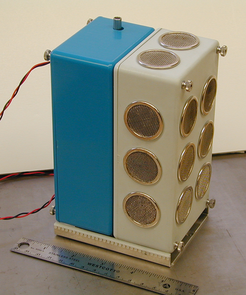 |
 |
A portable fuel cell developed by NASA/JPL
[link] |
This "carbon-air" fuel cell was built by William Jaques in the mid-1800s. It was based on an 1855 design by E. Becquerel and put out 1.5 kw. The electrolyte was molten KNO3 (hence the furnace) and the anode reaction was
C + 4OH– → CO2 + 2H2O + e–
|
Microbobial Fuel Cells
Certain types of bacteria are able to oxidize organic compounds to carbon dioxide while directly transferring electrons to electrodes. These so-called electricigen organisms may make it possible to convert renewable biomass and organic waste directly into electricity without the wasted energy and pollution produced by direct combustion. In one experiment, a graphite electrode immersed in ordinary mud (containing humic materials) was able to produce measurable amounts of electricity. For more information, see this article by Derek Loveley of U. Mass Amherst.
Smithsonian fuel cell project A well-designed site with information on many types of fuel cells and a nice section (with pictures) of early ones.
Other major fuel cell types A more compact site with good illustrations
What you need to know
Make sure you thoroughly understand the following essential ideas
which have been presented above. It is especially imortant that you
know the precise meanings of all the highlighted terms in the context of
this topic.- A battery is a galvanic cell in which some of the free energy change associated with a spontaneous electron-transfer reaction is captured in the form of electrical energy.
- A secondary or storage battery is one in which the electron-transfer reaction can be reversed by applying a charging current from an external source.
- A fuel cell is a special type of battery in which the reactants are supplied from an external source as power is produced. In most practical fuel cells, H+ ions are produced at the anode (either from H2 or a hydrocarbon) and oxygen from the air is reduced to H2O at the cathode.
- The cathodic reduction of O2 is kinetically limited, necessitating the use of electrode surfaces having high catalytic activity.
- The electrodes in batteries must have very high effective surface areas, and thus be highly porous. This requirement may conflict with the other important one of efficient diffusion of reactants and products in the narrow channels within the pores.
- Batteries and fuel cells designed to power vehicles and portable devices need to have high charge-to-weight and charge-tovolume ratios.
Concept Map
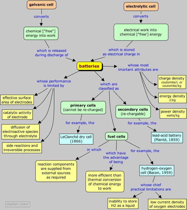
Corrosion can be defined as the deterioration of materials by
chemical processes. Of these, the most important by far is
electrochemical corrosion of metals, in which the oxidation process
M → M+ + e– is facilitated by the presence of a suitable electron acceptor, sometimes referred to in corrosion science as a depolarizer.
In a sense, corrosion can be viewed as the spontaneous return of metals to their ores; the huge quantities of energy that were consumed in mining, refining, and manufacturing metals into useful objects is dissipated by a variety of different routes.The economic aspects of corrosion are far greater than most people realize; according to a 2001 report, the cost of corrosion in the U.S. alone was $276 billion per year. Of this, about $121 billion was spent to control corrosion, leaving the difference of $155 billion as the net loss to the economy. Utilities, especially drinking water and sewer systems, suffer the largest economic impact, with motor vehicles and transportation being a close second.
Corrosion cells and reactions
The special characteristic of most corrosion processes is that the
oxidation and reduction steps occur at separate locations on the metal.
This is possible because metals are conductive, so the electrons can
flow through the metal from the anodic to the cathodic regions. The
presence of water is necessary in order to transport ions to and from
the metal, but a thin film of adsorbed moisture can be sufficient.
A corrosion system can be regarded as a short-circuited electrochemical cell in which the anodic process is something like
Fe(s) → Fe2+(aq) + 2 e–
and the cathodic steps can be any of
O2 + 2 H2O + 4e– → 4 OH–
H+ + e– → ½ H2(g)
M2+ + 2 e– → M(s)
where M is a metal. 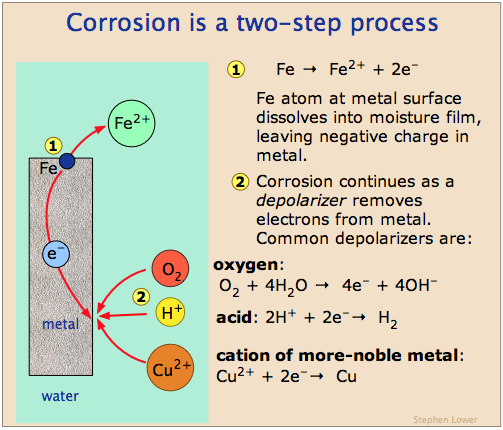 |
Electrochemical corrosion of iron
Corrosion often begins at a location (1)
where the metal is under stress (at a bend or weld) or is isolated from
the air (where two pieces of metal are joined or under a
loosely-adhering paint film.) The metal ions dissolve in the moisture
film and the electrons migrate to another location (2) where they are taken up by a depolarizer. Oxygen is the most common depolarizer; the resulting hydroxide ions react with the Fe2+ to form the mixture of hydrous iron oxides known as rust. |
Which parts of the metal serve as anodes and cathodes can depend on
many factors, as can be seen from the irregular corrosion patterns that
are commonly observed. Atoms in regions that have undergone stress, as
might be produced by forming or machining, often tend to have higher
free energies, and thus tend to become anodic.
If one part of a metallic object is protected from the atmosphere so that there is insufficient O2
to build or maintain the oxide film, this "protected" region will often
be the site at which corrosion is most active. The fact that such sites
are usually hidden from view accounts for much of the difficulty in
detecting and controlling corrosion.
 |
Schematic diagram of corrosion cells on iron [link]
|
Pitting corrosion
Most metals are covered with a thin oxide film which
inhibits anodic dissolution. When corrosion does occur, it sometimes
hollows out a narrow hole or pit in the metal. The bottoms of
these pits tend to be deprived of oxygen, thus promoting further growth
of the pit into the metal. |
 |
In contrast to anodic sites, which tend to be localized to specific regions of the surface, the cathodic part of the process can occur almost anywhere. Because metallic oxides are usually semiconductors, most oxide coatings do not inhibit the flow of electrons to the surface, so almost any region that is exposed to O2 or to some other electron acceptor can act as a cathode.
The tendency of oxygen-deprived locations to become anodic is the cause of many commonly-observed patterns of corrosion
Rusted-out cars and bathroom stains
 Anyone
who has owned an older car has seen corrosion occur at joints between
body parts and under paint films. You will also have noticed that once
corrosion starts, it tends to feed on itself. One reason for this is
that one of the products of the O2 reduction reaction is
hydroxide ion. The high pH produced in these cathodic regions tends to
destroy the protective oxide film, and may even soften or weaken paint
films, so that these sites can become anodic. The greater supply of
electrons promotes more intense cathodic action, which spawns even more
anodic sites, and so on.
Anyone
who has owned an older car has seen corrosion occur at joints between
body parts and under paint films. You will also have noticed that once
corrosion starts, it tends to feed on itself. One reason for this is
that one of the products of the O2 reduction reaction is
hydroxide ion. The high pH produced in these cathodic regions tends to
destroy the protective oxide film, and may even soften or weaken paint
films, so that these sites can become anodic. The greater supply of
electrons promotes more intense cathodic action, which spawns even more
anodic sites, and so on.A very common cause of corrosion is having two dissimilar metals in contact, as might occur near a fastener or at a weld joint. Moisture collects at the junction point, acting as an electrolyte and forming a cell in which the two metals serve as electrodes. Moisture and conductive salts on the outside surfaces provide an external conductive path, effectively short-circuiting the cell and producing very rapid corrosion; this is why cars rust out so quickly in places where salt is placed on roads to melt ice.
Dissimilar-metal corrosion can occur even if the two metals are not initially in direct contact. For example, in homes where copper tubing is used for plumbing, there is always a small amount of dissolved Cu2+ in the water. When this water encounters steel piping or a chrome-plated bathroom sink drain, the more-noble copper will plate out on the other metal, producing a new metals-in-contact corrosion cell. In the case of chrome bathroom sink fittings, this leads to the formation of Cr3+ salts which precipitate as greenish stains.
Control of corrosion
Since both the cathodic and anodic steps must take place for
corrosion to occur, prevention of either one will stop corrosion. The
most obvious strategy is to stop both processes by coating the object
with a paint or other protective coating. Even if this is done, there
are likely to be places where the coating is broken or does not
penetrate, particularly if there are holes or screw threads.A more sophisticated approach is to apply a slight negative charge to the metal, thus making it more difficult for the reaction M → M2+ + 2 e– to take place.
Sacrificial coatings
One way of supplying this negative charge is to apply a coating of a more active metal. Thus a very common way of protecting steel from corrosion is to coat it with a thin layer of zinc; this process is known as galvanizing.The zinc coating, being less noble than iron, tends to corrode selectively. Dissolution of this sacrificial coating leaves behind electrons which concentrate in the iron, making it cathodic and thus inhibiting its dissolution.
The effect of plating iron with a less active metal provides an interesting contrast. The common tin-plated can (on the right) is a good example. As long as the tin coating remains intact, all is well, but exposure of even a tiny part of the underlying iron to the moist atmosphere initiates corrosion. The electrons released from the iron flow into the tin, making the iron more anodic so now the tin is actively promoting corrosion of the iron! You have probably observed how tin cans disintegrate very rapidly when left outdoors.
Cathodic protection
A more sophisticated strategy is to maintain a continual negative electrical charge on a metal, so that its dissolution as positive ions is inhibited. Since the entire surface is forced into the cathodic condition, this method is known as cathodic protection. The source of electrons can be an external direct current power supply (commonly used to protect oil pipelines and other buried structures), or it can be the corrosion of another, more active metal such as a piece of zinc or aluminum buried in the ground nearby, as is shown in the illustration of the buried propane storage tank below. |
 |
Corrosion gallery
 |
Corrosion of a nail
The nails are immersed in agar which forms a moist
solid gel. The agar also contains phenolphthalein and hexacyanoiron(III)
Fe(CN6)– which forms a deep blue color ("prussian blue") in the presence of Fe2+.
The blue colors are clearly associated with those parts of the nail
that have been stressed, thus faciliting the anodic release of Fe2+ from the metal. The the pink color shows the cathodic regions that have been made alkaline by the reaction
O2 + 2 H2O + 4e– → 4 OH–
This clearly shows the separation between the anodic and cathodic processes in corrosion.
[Illustration from U of West Indies: link]
|
Water distribution main
If you live in the older part of a city where the mains
are 50-100 years old, the water you drink may well have passed through a
pipe in this condition! Severe corrosion like this is more common in
areas where the water is acidic. Such water comes from mountain snowmelt
and runoff, and usually acquires its acidity from dissolved atmospheric
carbon dioxide.Waters from rivers, lakes, and especially groundwaters from wells have usually been in sufficiently long contact with carbonate-containing sediments to have been neutralized. Water-works administrators like to make the water slightly alkaline and slightly supersaturated in calcium carbonate in order to maintain a thin coating of solid carbonate on the interior of the pipe which acts to protect it from corrosion. |
 |
Corrosion of reinforcing bars in concrete
All large concrete structures contain steel reinforcing
bars ("rebars") that help ensure structural integrity under varying
load conditions and especially during earthquakes. Intrusion of water,
even in the form of fog or mists, can lead to serious corrosion damage,
as seen in this picture of this column which supports a highway
overpass. |
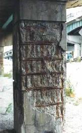 |
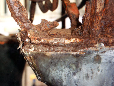 |
Corrosion at metallic joints The picture shows two steel structural members joined by cast iron flanges which have been bolted together. For some reason, one of the pieces has become more anodic than the other, leading to extensive corrosion of the upper part. |
| Bacterial-assisted corrosion This gas pipe was buried in a red soil that contained iron pyrites (FeS.) The bacterium thiobacillus ferrooxidans derives its energy by oxidizing Fe2+ to the more soluble Fe3+, transferring the electrons to O2. It also oxidizes the sulfur, producing sulfuric acid. The resulting chemical cocktail has eaten a hole into the pipe. |
|
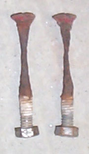 These
galvanized bolts were used to join wooden beams together. Subsequent
movement of the beams due to varying load conditions abraded the zinc
coating. A lack of oxygen near the centers of the bolts also likely
contributed to the corrosion by preventing the formation of a protective
oxide film. These
galvanized bolts were used to join wooden beams together. Subsequent
movement of the beams due to varying load conditions abraded the zinc
coating. A lack of oxygen near the centers of the bolts also likely
contributed to the corrosion by preventing the formation of a protective
oxide film. |
Pitting corrosion
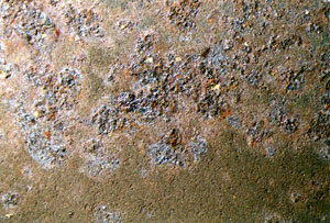 |

What you need to know
Make sure you thoroughly understand the following essential ideas
which have been presented above. It is especially imortant that you
know the precise meanings of all the highlighted terms in the context of
this topic.- Electrochemical corrosion of metals occurs when electrons from atoms at the surface of the metal are transferred to a suitable electron acceptor or depolarizer. Water must be present to serve as a medium for the transport of ions.
- The most common depolarizers are oxygen, acids, and the cations of less active metals.
- Because the electrons flow through the metallic object itself, the anodic and cathodic regions (the two halves of the electrochemical cell) can be at widely separated locations.
- Anodic regions tend to develop at locations where the metal is stressed or is protected from oxygen.
- Contact with a different kind of metal, either direct or indirect, can lead to corrosion of the more active one.
- Corrosion of steel can be inhibited by galvanizing, that is, by coating it with zinc, a more active metal whose dissolution leaves a negative charge on the metal which inhibits the further dissolution of Fe2+.
- Cathodic protection using an external voltage source is widely used to protect underground structures such as tanks, pipelines and piers. The source can be a sacrificial anode of zinc or aluminum, or a line-operated or photovoltaic power supply.
Concept Map
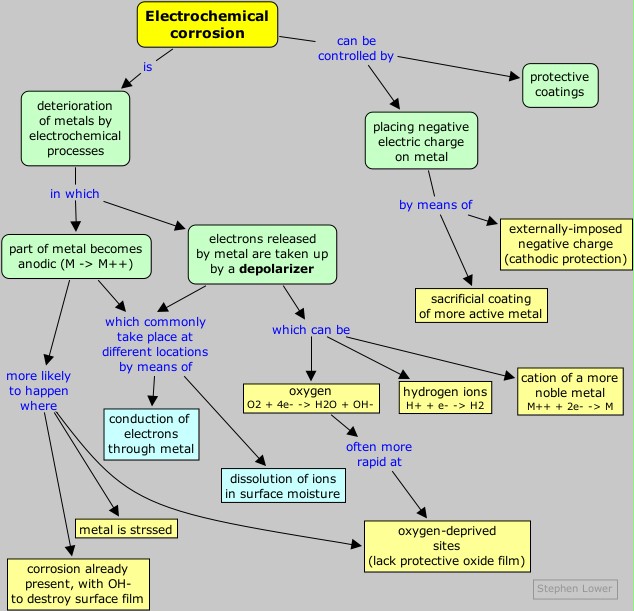
References
An overview of the different forms of corrosion (with photos)
Electrolysis
refers to the decomposition of a substance by an electric current. The
electrolysis of sodium and potassium hydroxides, first carried out in
1808 by Sir Humphrey Davey,
led to the discovery of these two metallic elements and showed that
these two hydroxides which had previously been considered
un-decomposable and thus elements, were in fact compounds:
Electrolysis of molten alkali halides is the usual industrial method of preparing the alkali metals:"By means of a flame which was thrown on a spoon containing potash, this alkali was kept for some minutes at a strong red heat, and in a state of perfect fluidity." One pole of a battery of copper-zinc cells was connected to the spoon, and the other was connected to platinum wire which dipped into the melt. "By this arrangement some brilliant phenomena were produced. The potash appeared to be a conductor in a high degree, and as long as the communication was preserved, a most intense light was exhibited at the negative wire, and a column of flame, which seemed to be owing to the development of combustible matter, arose from the point of contact." The flame was due to the combustion in the air of metallic potassium. In another experiment, Davey observed "small globules having a high metallic lustre, precisely similar in visible characters to quicksilver, some of which burnt with explosion and bright flame, as soon as they were formed, and others remained, and were merely tarnished, and finally covered by a white film which formed on their surfaces."
cathode:
|
Na+ + e– → Na(l) | E° = –2.71 v |
anode:
|
Cl– → ½ Cl2(g) + e– | E° = –1.36 v |
net:
|
Na+ + Cl– → Na(l) + ½ Cl2(g) | E° = –4.1 v |
cathode:
|
Ni2+ + 2 e– → Ni(s) | E° = –0.24 v |
anode:
|
2 Cl– → Cl2(g) + 2 e– | E° = –1.36 v |
net:
|
Ni2+ + 2 Cl– → Ni(s) + Cl2(g) | E° = –1.60 v |
A common misconception about electrolysis is that "ions are attracted to the oppositely-charged electrode." This is true only in the very thin interfacial region near the electrode surface. Ionic motion throughout the bulk of the solution occurs mostly by diffusion, which is the transport of molecules in response to a concentration gradient. Migration— the motion of a charged particle due to an applied electric field, is only a minor player, producing only about one non-random jump out of around 100,000 random ones for a 1 volt cm–1 electric field. Only those ions that are near the interfacial region are likely to undergo migration.
Electrolysis in aqueous solutions
Water is capable of undergoing both oxidation
H2O → O2(g) + 4 H+ + 2 e– E° = -1.23 v
and reduction
2 H2O + 2 e– → H2(g) + 2 OH– E° = -0.83 v
Thus if an aqueous solution is subjected to electrolysis, one or
both of the above reactions may be able to compete with the electrolysis
of the solute. For example, if we try to electrolyze a solution of sodium chloride, hydrogen is produced at the cathode instead of sodium:
cathode:
|
H2O + 2 e– → H2(g) + 2 OH– | E =+0.41 v ([OH–] = 10-7 M) |
anode:
|
Cl– → ½ Cl2(g) + e– | E° = –1.36 v |
net:
|
Cl– + H2O → 2 H2(g) + ½ Cl2(g) + 2 OH– | E = –0.95 v |
[This illustration is taken from the excellent
Purdue University Chemistry site] |
| Reduction of Na+ (E° = –2.7 v) is energetically more difficult than the reduction of water (–1.23 v), so in aqueous solution the latter will prevail. |
Electrolysis of water
Pure water is an insulator and cannot undergo signifigant electrolysis without adding an electrolyte. If the object is to produce hydrogen and oxygen, the electrolyte must be energetically more difficult to oxidize or reduce than water itself. Electrolysis of a solution of sulfuric acid or of a salt such as NaNO3 results in the decomposition of water at both electrodes:
cathode:
|
H2O + 2 e– → H2(g) + 2 OH– | E =+0.41 v ([OH–] = 10-7 M) |
anode:
|
2 H2O → O2(g) + 4 H+ + 2 e– | E° = -0.82 v |
net:
|
2 H2O(l) → 2 H2(g) + O2(g) | E = -1.23 v |
Faraday's laws of electrolysis
One mole of electric charge (96,500 coulombs), when passed through a cell, will discharge half a mole of a divalent metal ion such as Cu2+. This relation was first formulated by Faraday in 1832 in the form of two laws of electrolysis:-
The weights of substances formed at an electrode during
electrolysis are directly proportional to the quantity of electricity
that passes through the electrolyte.
- The weights of different substances formed by the passage of the same quantity of electricity are proportional to the equivalent weight of each substance.
Most stoichiometric problems involving electrolysis can be solved without explicit use of Faraday's laws. The "chemistry" in these problems is usually very elementary; the major difficulties usually stem from unfamiliarity with the basic electrical units:The equivalent weight of a substance is defined as the molar mass, divided by the number of electrons required to oxidize or reduce each unit of the substance. Thus one mole of V3+ corresponds to three equivalents of this species, and will require three faradays of charge to deposit it as metallic vanadium.
- current (amperes) is the rate of charge transport; 1 amp = 1 c/sec.
- power (watts) is the rate of energy production or consumption;
1 w = 1 J/sec = 1 volt-amp; 1 watt-sec = 1 J, 1 kw-h = 3600 J.
Problem Example 1
A metallic object to be plated with copper is placed in a solution of CuSO4.
a) To which electrode of a direct current power supply should the object be connected?
b) What mass of copper will be deposited if a current of 0.22 amp flows through the cell for 1.5 hours?
Solution:
a) Since Cu2+ ions are being reduced, the object acts as a cathode and must be connected to the negative terminal (where the electrons come from!)
b) The amount of charge passing through the cell is
(0.22 amp) × (5400 sec) = 1200 c
or
(1200 c) ÷ (96500 c F–1) = 0.012 F
Since the reduction of one mole of Cu2+ ion requires the addition of two moles of electrons, the mass of Cu deposited will be or
(1200 c) ÷ (96500 c F–1) = 0.012 F
(63.54 g mol–1) (0.5 mol Cu/F) (.012 F) = 0.39 g of copper
Problem Example 2
How much electric power is required to produce 1 metric ton
(1000 kg) of chlorine from brine, assuming the cells operate at 2.0
volts and assuming 100 % efficiency?
Solution:
Solution:
moles of Cl2 produced: (106 g) ÷ 70 g mol–1 = 14300 mol Cl2(In the last step, recall that 1 w = 1 j/s, so 1 kw-h = 3.6 Mj)
faradays of charge: (2 F/mol) × (14300 mol) = 28600 F
charge in coulombs: (96500 c/F) × (28600 F) = 2.76 × 10⁹ c
duration of electrolysis: (3600 s/h) x (24 h) = 86400 s
current (rate of charge delivery): (2.76 × 10⁹ amp-sec) ÷ (86400 sec) = 32300 amps
power (volt-amps): (2.0 v) × (32300 a) = 64.6 kw
energy in kW-h: (64.6 kw) × (24 h) = 1550 kw-h
energy in joules: (1550 kw-h) × (3.6Mj/kw-h) = 5580 Mj (megajoules)
Industrial electrolytic processes
For many industrial-scale operations involving the oxidation
or reduction of both inorganic and organic substances, and especially
for the production of the more active metals such as sodium, calcium,
magnesium, and aluminum, the most cost-effective reducing agent is
electrons supplied by an external power source. The two most
economically important of these processes are described below.The chloralkali industry
The electrolysis of brine is carried out on a huge scale for the industrial production of chlorine and caustic soda (sodium hydroxide). Because the reduction potential of Na+ is much higher than that of water, the latter substance undergoes decomposition at the cathode, yielding hydrogen gas and OH–.| anode reactions |
2 Cl– → Cl2(g) + 2 e– | -1.36 v | i |
| 4 OH– → O2(g) + 2 H2O + 4 e– | -0.40 v | ii | |
| cathode reactions |
Na+ + e– → Na(s) | -2.7 v | iii |
| H2O + 2 e– → H2(g) + 2 OH– | +.41 v | iv |
A comparison of the E°s would lead us to predict that the reduction (ii) would be favored over that of (i). This is certainly the case from a purely energetic standpoint, but as was mentioned in the section on fuel cells, electrode reactions involving O2 are notoriously slow (that is, they are kinetically hindered), so the anodic process here is under kinetic rather than thermodynamic control. The reduction of water (iv) is energetically favored over that of Na+ (iii), so the net result of the electrolysis of brine is the production of Cl2 and NaOH ("caustic"), both of which are of immense industrial importance:
2 NaCl + 2 H2O → 2 NaOH + Cl2(g) + H2(g)
 |
 |
A modern industrial chloralkali plant
|
Schematic diagram of a cell for the production of chlorine
|
Here is an excellent survey of industrial brine electrolysis from Case Western Reserve University
Electrolytic refining of aluminum

 Aluminum
is present in most rocks and is the most abundant metallic element in
the earth's crust (eight percent by weight.) However, its isolation is
very difficult and expensive to accomplish by purely chemical means, as
evidenced by the high E° (–1.66 v) of the Al3+/Al couple. For
the same reason, aluminum cannot be isolated by electrolysis of aqueous
solutions of its compounds, since the water would be electrolyzed
preferentially. And if you have ever tried to melt a rock, you will
appreciate the difficulty of electrolyzing a molten aluminum ore!
Aluminum was in fact considered an exotic and costly metal until 1886,
when Charles Hall (U.S.A) and Paul Hérault (France) independently developed a practical electrolytic reduction process.
Aluminum
is present in most rocks and is the most abundant metallic element in
the earth's crust (eight percent by weight.) However, its isolation is
very difficult and expensive to accomplish by purely chemical means, as
evidenced by the high E° (–1.66 v) of the Al3+/Al couple. For
the same reason, aluminum cannot be isolated by electrolysis of aqueous
solutions of its compounds, since the water would be electrolyzed
preferentially. And if you have ever tried to melt a rock, you will
appreciate the difficulty of electrolyzing a molten aluminum ore!
Aluminum was in fact considered an exotic and costly metal until 1886,
when Charles Hall (U.S.A) and Paul Hérault (France) independently developed a practical electrolytic reduction process.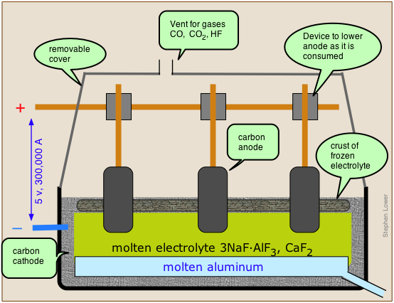
The Hall-Hérault process takes advantage of the principle that the melting point of a substance is reduced by admixture with another substance with which it forms a homogeneous phase. Instead of using the pure alumina ore Al2O3 which melts at 2050°C, it is mixed with cryolite, which is a natural mixture of NaF and AlF3, thus reducing the temperature required to a more manageable 1000°C. The anodes of the cell are made of carbon (actually a mixture of pitch and coal), and this plays a direct role in the process; the carbon gets oxidized (by the oxide ions left over from the reduction of Al3+ to CO, and the free energy of this reaction helps drive the aluminum reduction, lowering the voltage that must be applied and thus reducing the power consumption. This is important, because aluminum refining is the largest consumer of industrial electricity, accounting for about 5% of all electricity generated in North America. Since aluminum cells commonly operated at about 100,000 amperes, even a slight reduction in voltage can result in a large saving of power.
The net reaction is
2 Al2O3 + 3 C → 4 Al + 3 CO2
However, large quantities of CO and of HF (from the
cryolite), and hydrocarbons (from the electrodes) are formed in various
side reactions, and these can be serious sources of environmental
pollution.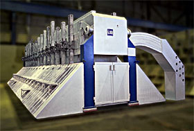
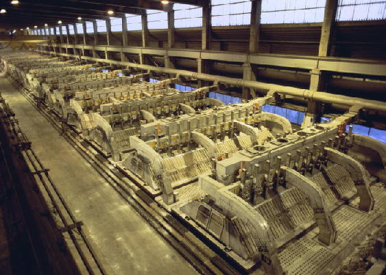
What you need to know
Make sure you thoroughly understand the following essential ideas
which have been presented above. It is especially imortant that you
know the precise meanings of all the highlighted terms in the context of
this topic.- In electrolysis, an external power source supplies the free energy required to drive a cell reaction in its non-spontaneous direction. An electrolytic cell is in this sense the opposite of a galvanic cell. In practice, the products of electrolysis are usually simpler than the reactants, hence the term electro-lysis.
- Transport of ions in the electrolyte in response to the potential difference between the electrodes ("drift") is largely restricted to the regions very close to the electrodes. Ionic transport in the greater part of the electrolyte is by ordinary thermal diffusion— the statistical tendency of concentrations to become uniform.
- When an aqueous solution is subjected to electrolysis, the oxidation or reduction of water can be a competing process and may dominate if the applied voltage is sufficiently great. Thus an attempt to electrolyze a solution of NaNO3 will produce only H2 and O2.
- A large number of electrolysis processes are employed by industry to refine metals and to produce both inorganic and organic products. The largest of these are the chloralkali industry (chlorine and "caustic"), and the refining of aluminum; the latter consumes approximately 5% of the electrical power generated in North America.
Concept Map
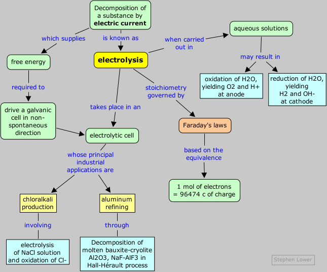
References
Electrolysis tutorial (with practice problems) from Purdue University
Hi Everybody I really found the information quite interesting and let me introduce myself.
ReplyDeleteWe are Gayatri Dyes & Chemicals leaders in providing raw materials for liquid sindoor and other cosmetic industry.All the chemicals and colours that we provide are cosmetics grade and Indian Pharma passed.We can help you to make the products from better to best.
Liquid Sindoor raw materials